Power transmission device for a vehicle
a transmission device and vehicle technology, applied in the direction of springs/dampers, gearing, couplings, etc., can solve the problems of difficult spring arrangement in the damper device, the weight of the damper device is greater, etc., to achieve the effect of reducing size and weight, facilitating rigidity during torque transmission, and reducing the size and weigh
- Summary
- Abstract
- Description
- Claims
- Application Information
AI Technical Summary
Benefits of technology
Problems solved by technology
Method used
Image
Examples
first embodiment
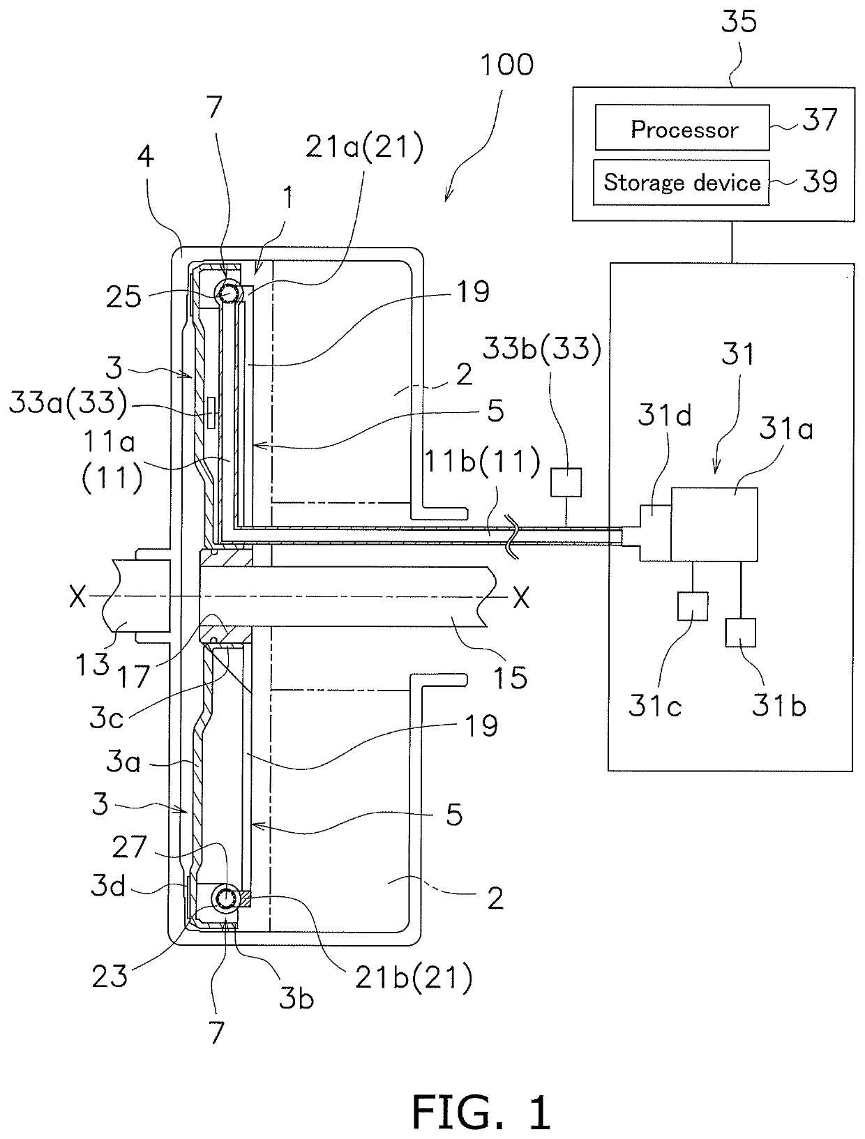
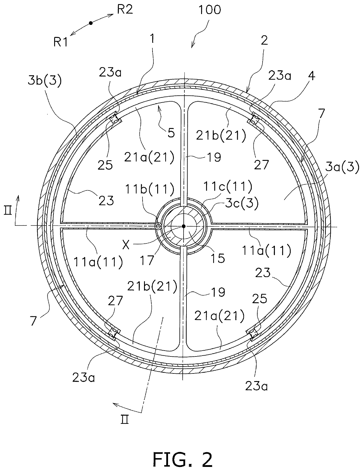
[0034]FIG. 1 is a cross-sectional view schematically showing the torque converter 100. FIG. 2 is a front view schematically showing the torque converter 100.
[0035]As shown in FIG. 1, the torque converter 100 includes a power transmission device 1 and a torque converter body 2. The torque converter body 2 is connected to the output shaft 15. A front cover 4 is fixed to the torque converter body 2. Since the configuration of the torque converter body 2 is substantially the same as the conventional configuration, the description thereof is omitted here.
[0036]As shown in FIG. 1, the power transmission device 1 includes an input rotating member 3 (an example of a first rotating member), an output rotating member 5 (an example of a second rotating member), a torque transmission portion 7, and a hydraulic pressure applying portion 31.
[0037]Specifically, the power transmission device 1 includes an input rotating member 3, an output rotating member 5, at least one torque transmission portion...
second embodiment
[0094]In the second embodiment, the setting mode of the average hydraulic pressure is different from that of the first embodiment. In the second embodiment, only the configuration different from the first embodiment will be described. The configuration omitted here conforms to the configuration of the first embodiment.
[0095]For example, as shown in FIG. 4, the hydraulic pressure applying portion 31 includes a hydraulic chamber 31a, an electric pump portion 31b, a relief valve 31c, a balance piston 31d, and a pressure sensor 31e. The pressure sensor 31e detects the hydraulic pressure in the hydraulic chamber 31a.
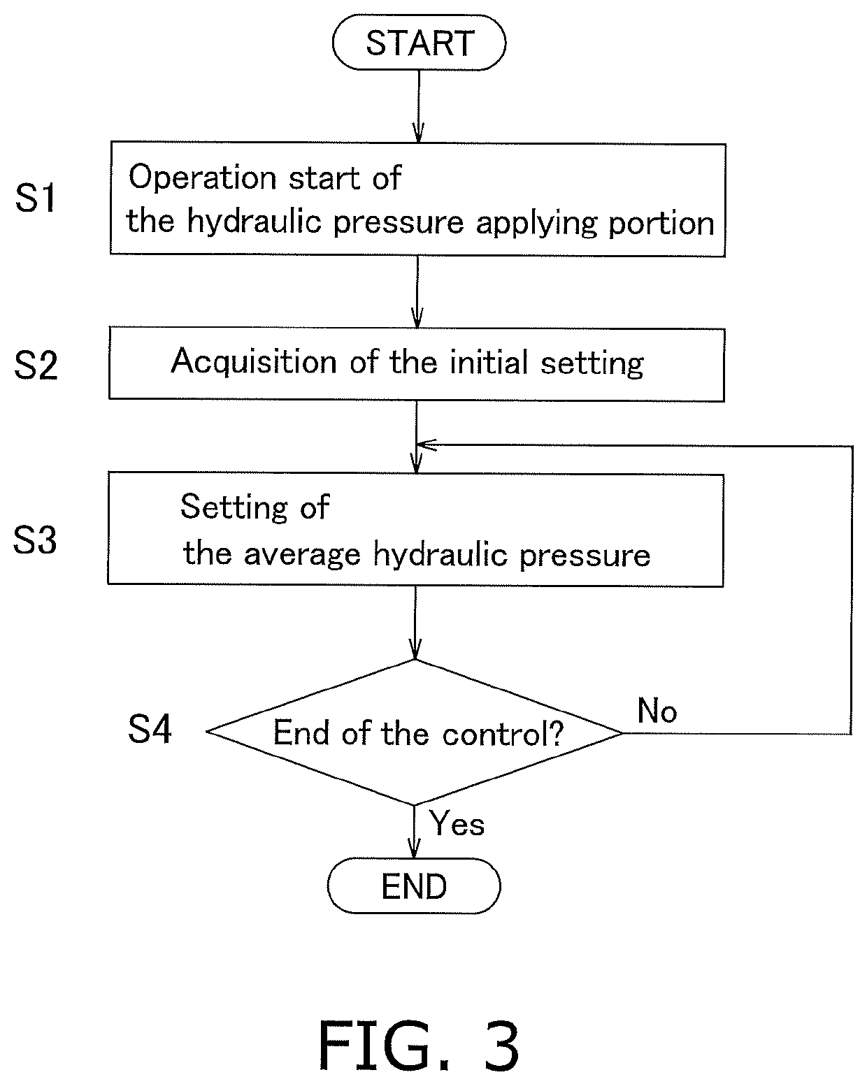
[0096]First, as shown in FIG. 5, in the same way as the first embodiment, the processor 37 instructs the hydraulic pressure applying portion 31 on the operation start command (S11). Thereby, the initial setting data is read from the storage device 39 and recognized by the processor 37 (S12). The initial setting data includes oil amount data of hydraulic fluid which is suppli...
third embodiment
[0127]In the third embodiment, the setting mode of the hydraulic pressure fluctuation is different from that of the first and second embodiments. In the third embodiment, only the configuration different from the first and second embodiments will be described. The configuration omitted here conforms to the configuration of the first and second embodiments.
[0128]In the third embodiment, the hydraulic pressure applying portion 31 applies hydraulic pressure to the hydraulic fluid of the torque transmission portion 7 and relieves the hydraulic pressure fluctuation of the hydraulic fluid of the torque transmission portion 7.
[0129]For example, as shown in FIG. 4, the hydraulic pressure applying portion 31 includes the hydraulic chamber 31a, the electric pump portion 31b, the relief valve 31c, the balance piston 31d, and the pressure sensor 31e. The pressure sensor 31e detects the hydraulic pressure of the hydraulic chamber 31a.
[0130]In this case, first, as shown in FIG. 6, the pressure s...
PUM
 Abstract
Description
Claims
Application Information
 - R&D
- Intellectual Property
- Life Sciences
- Materials
- Tech Scout
- Unparalleled Data Quality
- Higher Quality Content
- 60% Fewer Hallucinations
Browse by: Latest US Patents, China's latest patents, Technical Efficacy Thesaurus, Application Domain, Technology Topic, Popular Technical Reports.
© 2025 PatSnap. All rights reserved.Legal|Privacy policy|Modern Slavery Act Transparency Statement|Sitemap|About US| Contact US: help@patsnap.com


