Piping unit with heat exchange structure

a technology of heat exchange structure and piping unit, which is applied in the direction of pipes, pipes, machines/engines, etc., can solve the problems of difficulty in sufficient downsizing of a cooler, the heat dissipation effect cannot be achieved with conventional heat dissipation structures, and the cooler itself is downsized, so as to facilitate the downsizing of the cooler, the heat of heated fluid flowing, and the effect of reducing the resistance of air flow

Inactive Publication Date: 2020-04-30
ROKI CO LTD +1
View PDF0 Cites 2 Cited by
  • Summary
  • Abstract
  • Description
  • Claims
  • Application Information

AI Technical Summary

Benefits of technology

[0015]Since the piping unit according to the present invention has a heat exchange structure on its inner peripheral surface, it can efficiently dissipate the heat of heated fluid flowing in the piping unit or transfer heat to cooled fluid without degrading air flow resistance. The temperature of fluid to be introduced into a cooler and the like can thereby be decreased or increased, so that downsizing of the cooler is facilitated without lowering of cooling efficiency of the cooler and the like.

Problems solved by technology

Since these conventional coolers have a function of cooling introduced fluid, they require securing of a certain contact area to achieve a desired cooling effect, having a problem of difficulty in downsizing the cooler itself.
However, sufficient heat dissipation effect cannot be achieved with conventional heat dissipation structures, such as one with a piping unit wrapped with heat insulator or one with an increased contact area provided by an increased surface roughness of an outer surface of a piping unit.
Thus, there has been the problem of difficulty in sufficient downsizing of a cooler and still being unable to reduce the cooler size.

Method used


Image

  • Piping unit with heat exchange structure
  • Piping unit with heat exchange structure
  • Piping unit with heat exchange structure

Examples


example

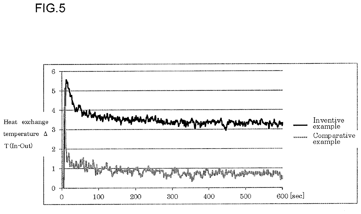
[0036]FIG. 5 shows results of measurement of heat exchange temperatures at a fluid temperature of 90° C. for an example of a piping unit with the heat exchange structure 20 according to this embodiment and a conventional piping unit as a comparative example without the heat exchange structure. As is apparent from FIG. 5, it can be seen that the heat exchange temperature in the example indicates that the heat exchange effect is higher than the comparative example by about 2 to 3.5° C. from soon after a start of measurement, and that the heat exchange effect is retained after elapse of 600 seconds.

[0037]As to the air flow resistance, as shown in FIG. 6, the example and the comparative example have similar levels of progression of air flow resistance even with increase or decrease in a flow rate of fluid, confirming that the formation of the heat exchange structure on the inner peripheral surface does not affect the air flow resistance.

[0038]Further, FIG. 7 shows the results of measure...


PUM

PropertyMeasurementUnit
depthaaaaaaaaaa
temperatureaaaaaaaaaa
heat exchange temperatureaaaaaaaaaa

Abstract

The present invention provides a piping unit that facilitates downsizing of a cooler by decreasing the temperature of fluid to be introduced into the cooler without reducing the cooling effect of a cooler. A piping unit is for introduction of heated fluid into a cooler, the piping unit being formed from synthetic resin and including a heat exchange structure on an inner peripheral surface.

Description

BACKGROUND OF THE INVENTIONField of the Invention[0001]The present invention relates to a piping unit for introduction of fluid, and more particularly to a piping unit having a heat exchange structure for dissipating heat of heated fluid before introduction of the heated fluid into a cooler and the like or for transferring heat to cooled fluid before introduction of the cooled fluid.Description of the Related Art[0002]Known conventional devices for cooling heated fluid, such as air and coolant, in an internal combustion engine or the like include cooling devices that cool fluid using a cooler such as an intercooler or a radiator.[0003]As shown in Japanese Patent Laid-Open No. 2007-182871, for instance, a piping structure that directs pressurized air from a supercharger into an intercooler for cooling therein is known. The piping structure shown in Japanese Patent Laid-Open No. 2007-182871 has strength enough for preventing deformation under pressurized air having a pressure increase...

Claims


Application Information

Patent Timeline
Patent Type & Authority Applications(United States)
IPC IPC(8): F16L53/70F16L9/22F16L9/127
CPCF16L9/127F16L53/70F16L9/22F16L53/75F16L53/30F16L43/008F16L9/006F02B29/0456F02B29/0412Y02T10/12B60H1/00571B60H1/00335B60H1/00328B60H1/00564B60K13/02B60K11/02
Inventor AKITA, TAKAHISAHIRAI, MASAHARUUCHIYAMA, AKIRAYANO, YUICHIROUSUI, HIDEMASAABE, YUTA
Owner ROKI CO LTD
Why Eureka
Try Eureka