Receiver, communication system, and method implemented by computer for enabling both analog and digital beamforming in communication system

a communication system and receiver technology, applied in diversity/multi-antenna systems, multi-frequency code systems, baseband system details, etc., can solve problems such as weak diffraction, high path loss in free space, and high penetration loss through building materials, so as to reduce the overhead of csi feedback, reduce the overhead of feedback, and maximize the sum rate of the system

Active Publication Date: 2020-04-30
MITSUBISHI ELECTRIC CORP
View PDF0 Cites 12 Cited by
  • Summary
  • Abstract
  • Description
  • Claims
  • Application Information

AI Technical Summary

Benefits of technology

[0043]In the present invention, since the computations in RF domain and in base band domain are separated, the signaling overhead for the CSI feedback is reduced.
[0044]Indeed, after the computation of the RF precoder and combiner, the equivalent user channel, which is the user channel after RF beamforming and combining, is fed back to the transmitter. Since the number of transmit and receive RF chai...

Problems solved by technology

Millimeter wave propagation is especially characterized by high path loss in free space, high penetration loss through building materials, weak diffraction, and vulnerability to blockage.
This design of transmitter/receiver precoders and combiners in systems with large antenna arrays is a quite difficult task.
In the case of systems with large antenna arrays, since the high bandwidth mixed-signal components are expensive and consume lots of power, the number of Radio Frequency (RF) chains at the transceiver needs to be smaller than the number of antennas.
Besides the choice of analog or hybrid architecture, knowing that those architectures are generally implemented with devices such as phase shifters, switches or optical lenses, particular architecture embodiment and the constraints on the implementation devices also lead to additional constraints on the tra...

Method used


Image

  • Receiver, communication system, and method implemented by computer for enabling both analog and digital beamforming in communication system
  • Receiver, communication system, and method implemented by computer for enabling both analog and digital beamforming in communication system
  • Receiver, communication system, and method implemented by computer for enabling both analog and digital beamforming in communication system

Examples


Embodiment Construction

[0163]Expressions such as “comprise”, “include”, “incorporate”, “contain”, “is” and “have” are to be construed in a non-exclusive manner when interpreting the description and its associated claims, namely construed to allow for other items or components which are not explicitly defined also to be present. Reference to the singular is also to be construed in be a reference to the plural and vice versa.

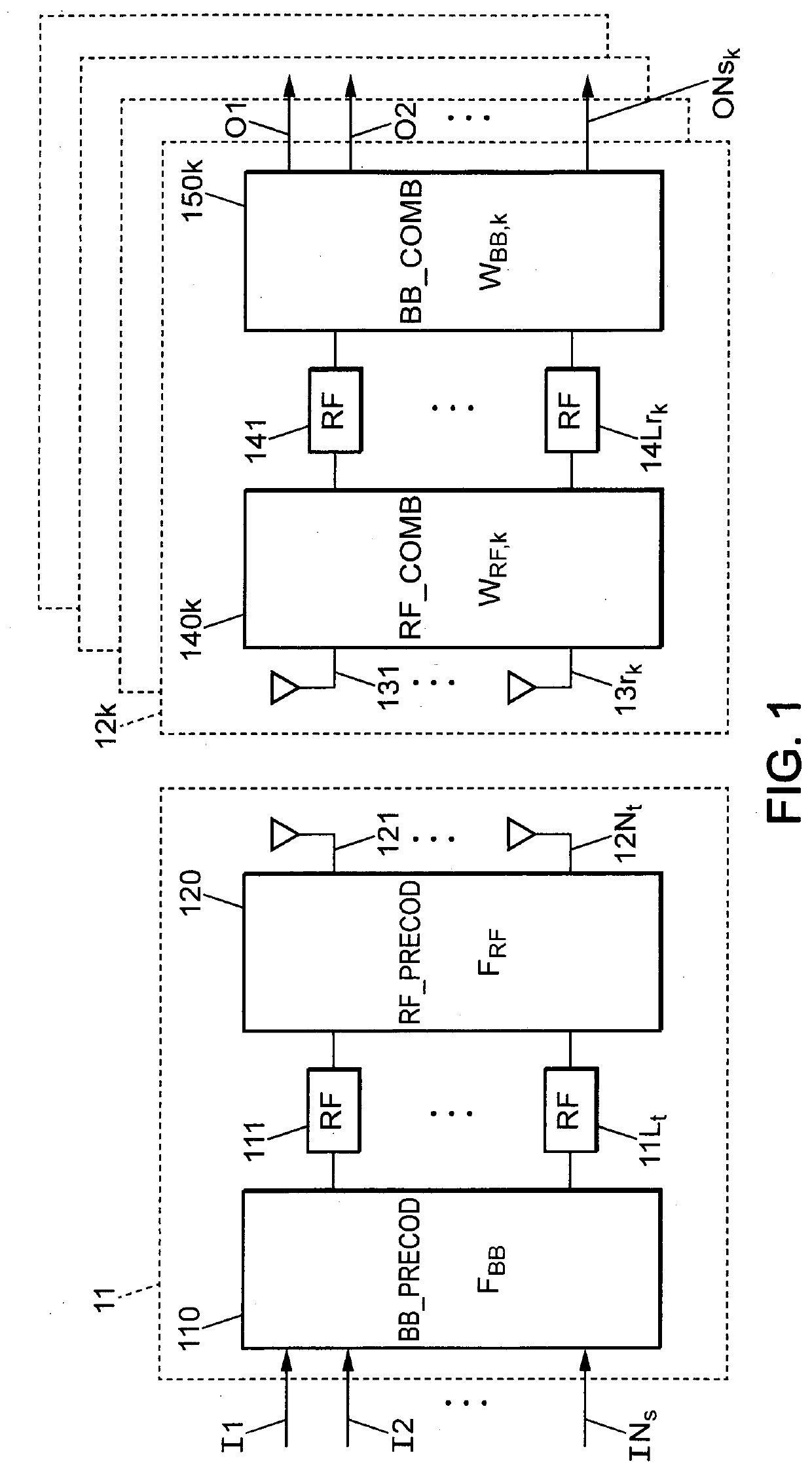
[0164]FIG. 1 represents an example of system supporting both analog and digital beamforming in which the present method can be performed.

[0165]According to FIG. 1, the system includes a transmitter 11 equipped with Nt transmit antennas (or “transmitting antennas”, or “transmitter antennas”) 121, . . . , 12Nt, wherein the transmitter 11 is able to jointly serve K (with K≥2) receivers 12k.

[0166]Each receiver 12k is equipped with Nrk receive antennas (or “receiving antennas”, or “receiver antennas”) 131, . . . , 13rk and is able to receive Nsk data streams from the transmitter 11.

[0167]Th...


PUM


Abstract

A method for enabling hybrid beamforming in a communication system including a transmitter being able to serve a plurality of receivers, wherein a frequency band comprises at least one subcarrier, wherein each receiver is associated to a set Cprec,k of analog precoiling codewords, said method comprising: —for each receiver, computing (202) an analog precoding matrix FRF k associated to said receiver; said computation (202) comprising: /a/ for each subcarrier, performing (202a) a Singular Value Decomposition, SVD, on a channel matrix associated to said receiver and to said each subcarrier; /b/ for each subcarrier, determining a first decomposition matrix Vk(1) based on the relative SVD; /c/ determining (303) an analog precoding codeword which optimizes a first function g1(Vk(1), . . . , Vk(L), F) of Vk(1), . . . , Vk(L) and F, for a plurality of F E Cprec,k, wherein L denotes a number of subcarriers.

Description

TECHNICAL FIELD[0001]The present invention relates to hybrid beamforming in a multi-user multi-antenna system, for instance a Multiple-Input / Multiple-Output (MIMO) system, and more specifically to the analog and digital precoders and combiners in such a system.BACKGROUND ART[0002]Millimeter wave (mmWave) wireless communication, which makes use of carrier frequencies going from 30 gigahertz (GHz) to 300 GHz, is expected to be a key feature, for instance, for future 5G cellular systems. A major benefit of using such high frequencies is the availability of much greater spectrum for higher data rates.[0003]Millimeter wave propagation is especially characterized by high path loss in free space, high penetration loss through building materials, weak diffraction, and vulnerability to blockage. Therefore, highly directional adaptive antenna arrays at both transmission and reception sides have to be used for compensating propagation impairments and enabling cellular coverage over distances o...

Claims


Application Information

Patent Timeline
IPC IPC(8): H04B7/0456H04B7/06H04L27/26H04L25/02H04B7/0417
CPCH04B7/0478H04L25/0248H04L27/2644H04B7/0617H04B7/0417H04B7/0634H04L25/03343
Inventor LI, QIANRUI
Owner MITSUBISHI ELECTRIC CORP
Why Eureka
Try Eureka