Methods and systems for guidance in cardiac resynchronization therapy

a technology of resynchronization therapy and methods, applied in the field of medical imaging, can solve the problems of delayed activation of the left ventricle, marked reduction of signal amplitude, and difficulty in detecting speckles based on echocardiography

Active Publication Date: 2020-05-07
PIE MEDICAL IMAGING
View PDF0 Cites 5 Cited by
  • Summary
  • Abstract
  • Description
  • Claims
  • Application Information

AI Technical Summary

Benefits of technology

[0034]According to an aspect, an electro anatomic mapping (EAM) model including 3D coronary vein anatomy and electrical activation timing is received and registered with the 3D roadmap model to determine optimal left ventricle lead position or positions.
[0035]In an embodiment, patient specific x-ray image data such as an x-ray venogram are received and registered with the 3D roadmap model to outline optimal left ventricle lead position or positions.

Problems solved by technology

A blockage of the left branch bundle (LBBB) results consequently in a delayed activation of the left ventricle.
Despite the striking effectiveness of CRT in improving clinical outcomes as well as prognosis, a substantial proportion, up to 40% of patients who receive a CRT device, fails to benefit from this therapy, the so called ‘non-responders’.
However, speckle tracking based on echocardiography can be technically challenging, particularly in regions of scar (myocardium infarct) in which signal amplitude is markedly reduced due to the physical limitations of ultrasound.
Furthermore, ultrasound is very operator depending resulting in a high variability.
Suboptimal position of the LV lead: The implantation of a LV lead in patients is technically a rather complex procedure.
Implantation training for CRT has a significant learning curve.
Duration of implantation and fluoroscopic time can be substantial and implantation failure can be due to several reasons, such as inability to intubate the coronary sinus, unstable guiding delivery catheter, coronary vein stenosis or occlusion.
However, echocardiographic strain analysis may not be the best technique to assess mechanical activation as well as regions of myocardium scar due to physical limitations of ultrasound and its high operator dependency.
However, this method does not take into consideration any location of myocardium infarct and furthermore, the guidance is based on result obtained by activating the device at a random location within the coronary vein, making the procedure still trial and error.

Method used


Image

  • Methods and systems for guidance in cardiac resynchronization therapy
  • Methods and systems for guidance in cardiac resynchronization therapy
  • Methods and systems for guidance in cardiac resynchronization therapy

Examples


Embodiment Construction

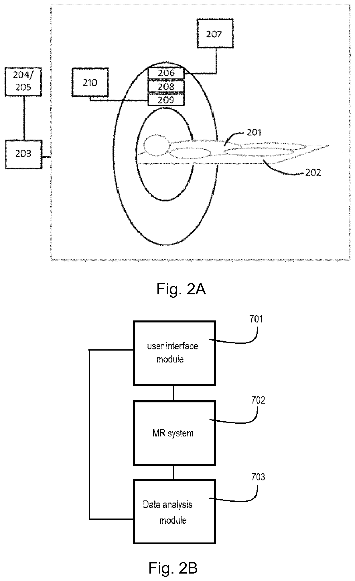
[0073]A magnetic resonance imaging apparatus comprises an imaging unit configured to carry out sequential imaging. The apparatus applies a radiofrequency magnetic field onto a subject (i.e. patient) placed in a static magnetic field. A magnetic resonance signal generated from the subject is detected due to the application of the radio-frequency magnetic field. Using the detected signals an image is created. The magnetic resonance imaging apparatus also includes a gradient coil that adds spatial positional information to a magnetic resonance signal by applying a gradient magnetic field onto the subject. Using different combinations of radiofrequency pulses and gradients, different MRI sequences can be made. An MRI pulse sequence is a programmed set of changing magnetic gradients. Different pulse sequences allow the radiologist to image the same tissue in various ways, and combinations of sequences reveal important diagnostic information. FIG. 2A illustrates an example of a high-level...


PUM


Abstract

A method for providing guidance in Cardiac Resynchronization Therapy (CRT) comprising: a) providing image data sets of the heart of a patient; b) creating a three-dimensional (3D) anatomical model of the cardiac structures; c) calculating myocardium infarct scar distribution; d) calculating heart mechanical activation data; e) superimposing the scar distribution and the mechanical activation data on the 3D anatomical model to obtain a 3D roadmap model including anatomical geometry and mechanical activation data. A corresponding device and computer program are also model disclosed.

Description

FIELD OF THE INVENTION[0001]The present disclosure relates to the technical field of medical imaging, particularly to the field of electrophysiology, although it can find application in any field where there is the need to pre-procedural and or procedural guidance.STATE OF THE ART[0002]Heart failure is a common disease in the Western world and rising up to 10% among people of 70 years and older. Heart failure is defined as a clinical syndrome characterized by clinical symptoms of breathlessness, ankle swelling, and fatigue. Approximately 25%-30% of patients diagnosed with heart failure demonstrate electrical conduction abnormalities of the hearth. Cardiac electrophysiology is a sub-discipline of cardiology enclosing the diagnosis and treatment of abnormal heart rhythms, also known as cardiac arrhythmia, cardiac dysrhythmia or irregular heartbeat. Cardiac arrhythmia is a group of conditions in which the heartbeat is irregular due to problems with the electrical conduction system of t...

Claims


Application Information

Patent Timeline
Patent Type & Authority Applications(United States)
IPC IPC(8): A61B34/10A61B6/00A61B5/00A61B5/055A61B5/0452G06T17/00G06T7/00G06T7/11
CPCA61B5/0044A61B6/503G06T2207/30048G06T17/00G06T2207/10081A61B2034/105A61B5/055A61B2576/023G06T7/0012A61N1/362A61B6/481A61B5/0452A61B2090/367G06T7/11G06T2207/10088A61B34/10A61B6/4417G16H30/40A61B5/7425A61B2034/104G06T2207/30101G06T2207/10116G06T2207/20081G06T2207/10104G06T2207/10108G06T2207/10132G06T2207/20084A61B5/349
Inventor ABEN, JEAN-PAULBOUWMAN, CHRIS
Owner PIE MEDICAL IMAGING
Why Eureka
Try Eureka