
Manufacturing method and structure of wheel rim

a manufacturing method and wheel rim technology, applied in the field of manufacturing methods and wheel rim structures, can solve the problems of lack of ductility of carbon fibers, high defect rates of existing carbon fiber wheel rims, and complicated process for attaching carbon fiber fabrics to the surface of airbags, so as to reduce the manufacturing cost of wheels, improve the manufacturing efficiency and yield of wheels, and lighten the wheel weight

Inactive Publication Date: 2020-05-14
ALEX GLOBAL TECH
View PDF4 Cites 0 Cited by
  • Summary
  • Abstract
  • Description
  • Claims
  • Application Information

AI Technical Summary

Benefits of technology

The present invention aims to improve the efficiency, yield, safety and durability of wheel manufacturing. It reduces the weight and manufacturing cost of the wheel, while improving the manufacturing efficiency and yield of the wheel. Additionally, it prevents tire leaks or falls off by securely engaging the tire's lips with the rim. The rim is made of metal and carbon fiber materials, which makes it rigid but ductile, able to withstand road shocks and improving the safety and durability of the wheel.

Problems solved by technology

However, due to the soft texture of the airbag, the procedure for attaching the carbon fiber fabrics to the surface of the airbag is quite complicated and time consuming.
Especially, the carbon fiber fabrics are difficult to flatly paste on the soft airbag, resulting in high defect rates in existing carbon fiber wheel rims.
After the plural layers of carbon fiber fabrics are stacked to form a rim shape, the carbon fibers must be hardened by a process such as heating which results in a lack of ductility of the carbon fibers.
In such a case, as the carbon fiber wheel rims of the bicycle is driven to rotate on an uneven road and is subjected to shocks, e.g. vibration, the carbon fiber wheel rim cannot withstand the impact force, and is easily broken or damaged.
Furthermore, the upper ends of the two lateral walls of the abovementioned carbon fiber wheel rim cannot be formed with convex ribs for engaging with tire lips, and the flanges can be formed only by thickening the stack of carbon fiber fabrics.
As a result, the bonding of the existing carbon fiber wheel rim and the tire is not stable enough, and the tire is easily detached from the carbon fiber wheel rim.
When the carbon fiber wheel rim is used as a tubeless wheel rim, it may cause air leakage due to poor adhesion, which affects the safety of bicycle riders.

Method used


Image

  • Manufacturing method and structure of wheel rim
  • Manufacturing method and structure of wheel rim
  • Manufacturing method and structure of wheel rim

Examples


Embodiment Construction

[0013]Hereinafter, an exemplary embodiment of the present invention will be described in detail with reference to the accompanying drawings.

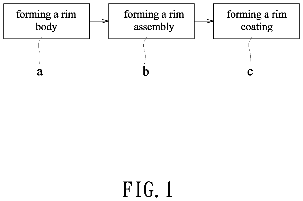
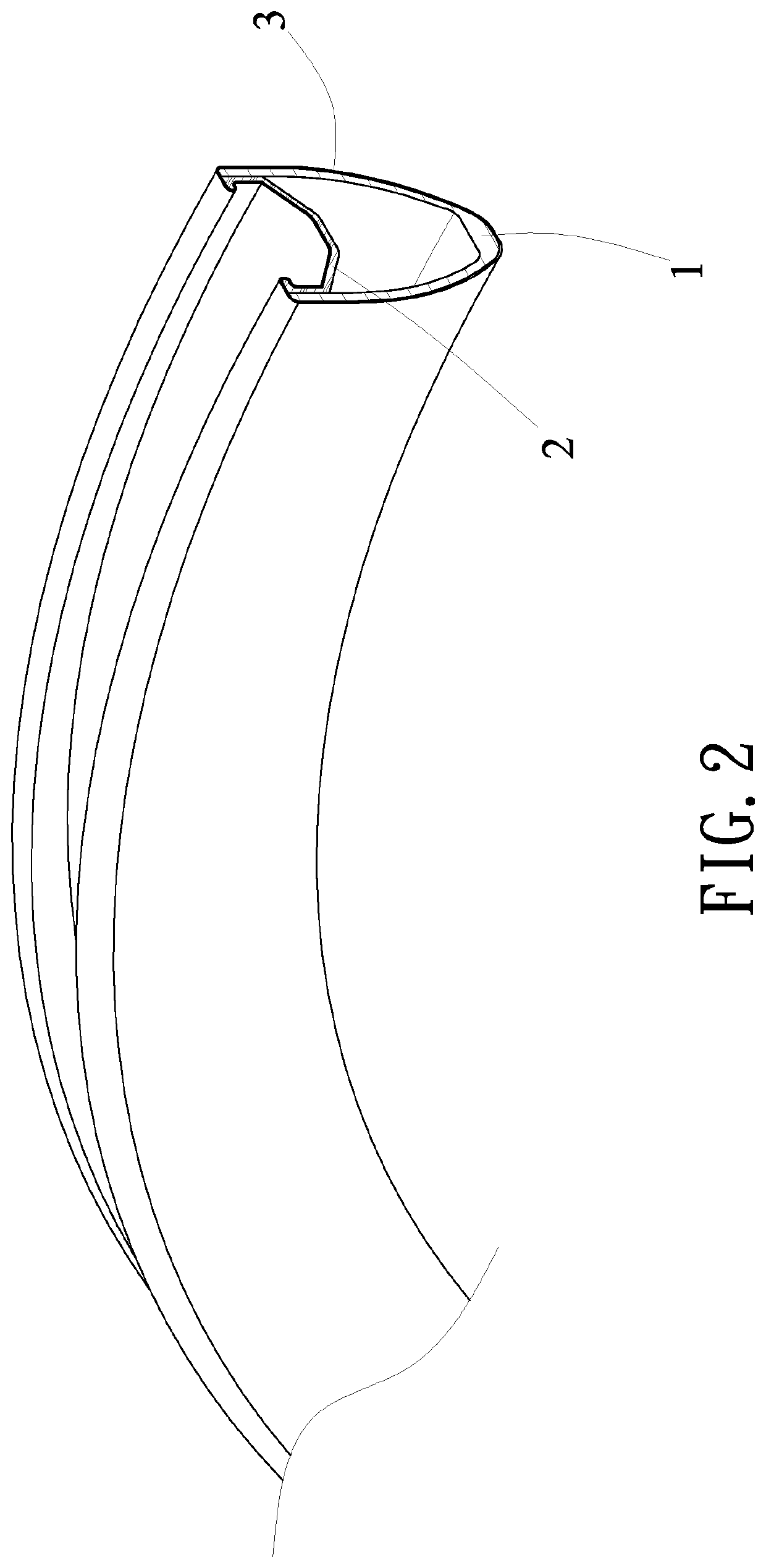
[0014]As showed in FIG. 1 and FIG. 2, a manufacturing method and a structure of a wheel rim according to the present invention are disclosed herein. The manufacturing method mainly comprises the steps of (a) forming a rim body, (b) forming a rim assembly, and (c) forming a rim coating.

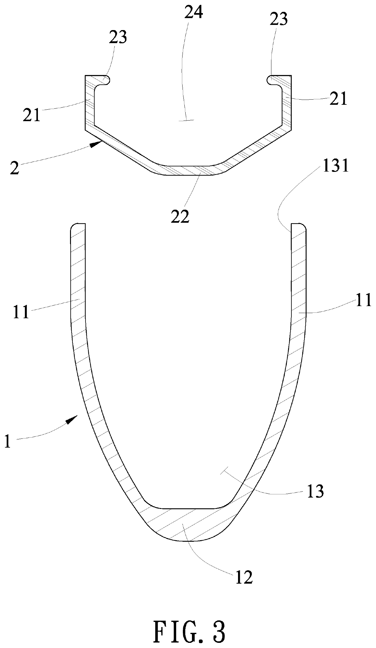
[0015]The step (a) comprises preparing a molding die having a cavity and coating plural layers of carbon fiber material in the cavity for hardening and shaping by heating to form a rim body (1). Preferably, the carbon fiber material is a carbon fiber fabric. Referring to FIG. 3, the rim body (1) has two lateral walls (11) opposite to each other, a bottom wall (12) for connecting lower ends of the two lateral walls (11), and an accommodating space (13) defined by the two lateral walls (11) and the bottom wall (12). The accommodating space (13) has an opening (131) f...


PUM

PropertyMeasurementUnit
Structureaaaaaaaaaa

Abstract

The invention relates to a manufacturing method and a structure of a wheel rim. The manufacturing method mainly comprises the steps of forming a rim body made of a carbon fiber material in a cavity of a molding die; forming a rim assembly by extruding a metal material and assembling the rim assembly to the rim body; and forming a rim coating by tightly encapsulating a carbon fiber material on a surface of the rim body assembled with the rim assembly.

Description

BACKGROUND OF THE INVENTION1. Field of the Invention[0001]The present invention relates to a manufacturing method and a structure of a wheel rim which can improve the manufacturing efficiency, yield, safety and durability of a wheel and reduce the weight and manufacturing cost of the wheel.2. Description of Related Art[0002]Generally, the existing carbon fiber wheel rim is mainly inflated by an annular airbag, and then an outer surface of the airbag is sequentially coated with plural layers of carbon fiber fabrics. However, due to the soft texture of the airbag, the procedure for attaching the carbon fiber fabrics to the surface of the airbag is quite complicated and time consuming. Especially, the carbon fiber fabrics are difficult to flatly paste on the soft airbag, resulting in high defect rates in existing carbon fiber wheel rims.[0003]After the plural layers of carbon fiber fabrics are stacked to form a rim shape, the carbon fibers must be hardened by a process such as heating ...

Claims


Application Information

Patent Timeline
IPC IPC(8): B21D53/30B60B3/02B21K1/38
CPCB60B3/02B21K1/38B21D53/30B60B3/001B21D53/86B21C23/08B29L2031/32B60B21/04B60B21/025B60B2320/14B60B5/02B60B1/003B60B2310/321B60B21/12B60B2310/30B60B2360/10B60B2360/30B60B2900/111
Inventor CHEN, WEI-CHIN
Owner ALEX GLOBAL TECH
Learn More