
Valve assembly

a valve body and assembly technology, applied in the field of valve assembly, can solve the problems of difficult to form grooves or protrusions in the valve body, easy to break, and limited connection methods with the inlet and outlet pipes made of steel pipes, so as to reduce volume and weight, increase durability, and not easily broken or deformed in operation.

Active Publication Date: 2020-05-14
DO QOOM CORP LTD
View PDF0 Cites 1 Cited by
  • Summary
  • Abstract
  • Description
  • Claims
  • Application Information

AI Technical Summary

Benefits of technology

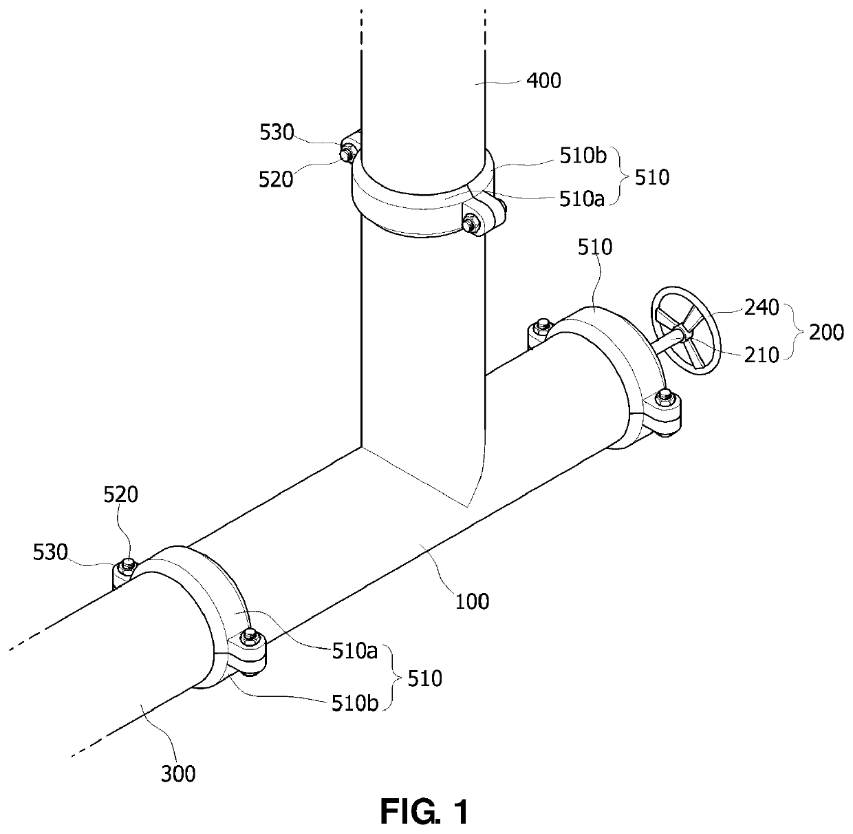
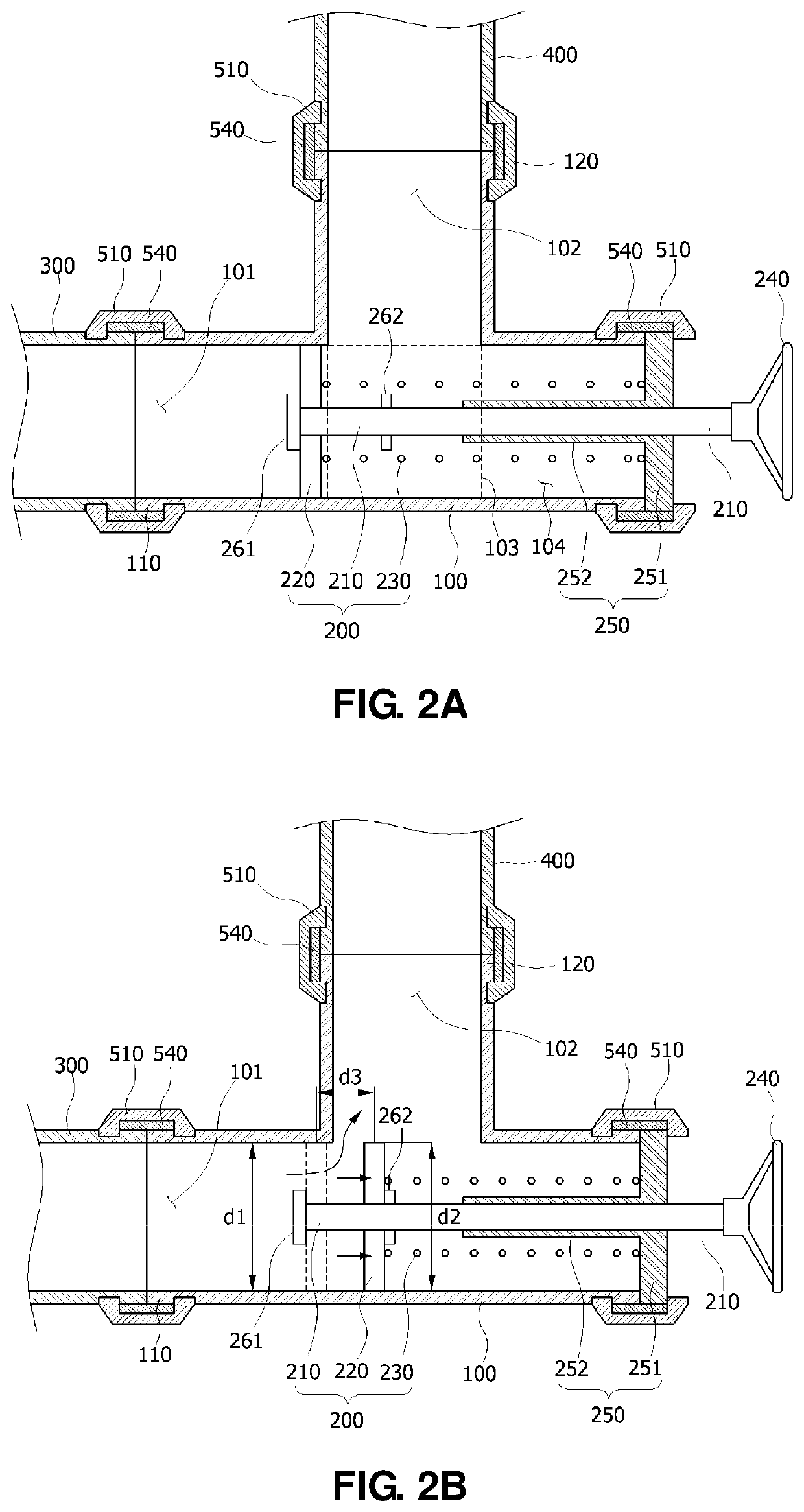
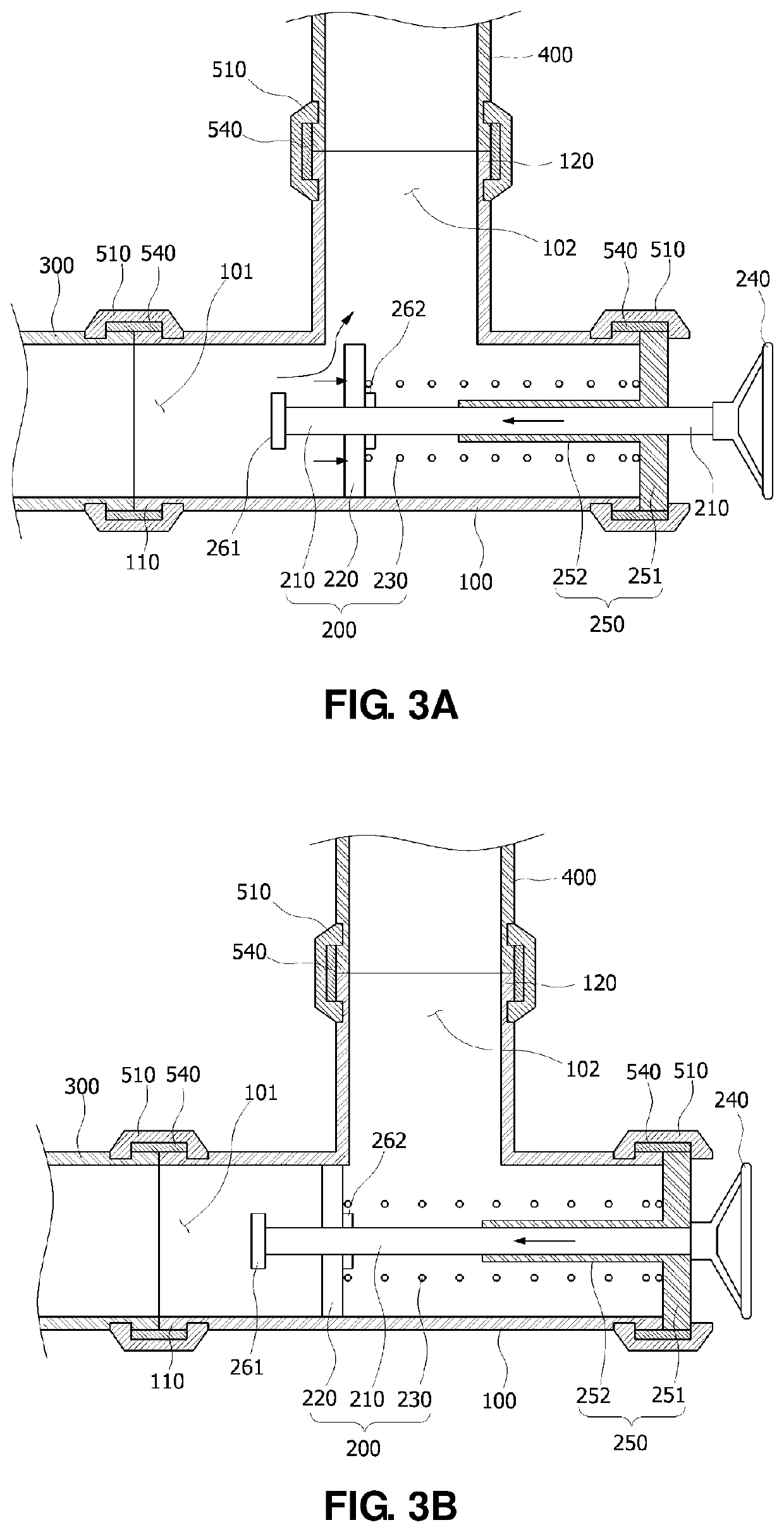
The present invention provides a valve assembly made of a steel or stainless-steel pipe, which has reduced size and weight, increased durability, and is resistant to deformation during operation. Compared to conventional valve bodies made of cast iron, the valve assembly is more efficient and cost-effective to manufacture. The valve assembly includes a valve body with an inlet, space, and outlet, and an opening and closing unit to control the fluid path. The valve body is connected to the inlet and outlet pipes through flanges, which are fastened with bolts. The valve assembly is not easily broken or deformed and is highly durable.

Problems solved by technology

However, the valve body made of cast iron is vulnerable to temperature changes and impacts (internal hydraulic impacts and external impacts) and thus may be easily broken when the temperature changes are repeated.
Further, in the case of the valve body made of the cast iron, a connection method with the inlet and outlet pipes made of the steel pipe is limited to a connection method using flanges.
This is because the valve body made of the cast iron may not be welded together with the inlet and outlet pipes made of steel pipes, and it is difficult to form grooves or protrusions in the valve body made of the cast iron, and thus the valve body may not be connected to the inlet and outlet pipes even by a ring joint method or a groove joint method.
Accordingly, in the case of the conventional valve body made of the cast iron, since the valve body is bulky and heavy, and vulnerable to the temperature changes, the valve body may easily be broken and may be connected to the inlet pipe or the outlet pipe only through the flanges, which causes an increase in the number of work processes, thereby increasing working time and manufacturing costs.

Method used


Image

  • Valve assembly
  • Valve assembly
  • Valve assembly

Examples


Embodiment Construction

[0034]Hereinafter, exemplary embodiments of the present invention will be described in detail with reference to the accompanying drawings so that those of ordinary skill in the art can easily implement them. The present invention may be embodied in many different forms and is not limited to the embodiments set forth herein.

[0035]For clarity, a description of parts not related to describing the present invention is omitted here, and the same reference numerals are allocated to the same or similar components throughout the disclosure.

[0036]Components having the same structure in various embodiments will be allocated the same reference numeral and explained only in a representative embodiment, and components which are different from those of the representative example will be described in the other embodiments.

[0037]As used herein, when an element is referred to as being “connected to” another element, the element can be directly connected to the other element or be indirectly connecte...


PUM

PropertyMeasurementUnit
diametersaaaaaaaaaa
circumferencesaaaaaaaaaa
flow rateaaaaaaaaaa

Abstract

A valve assembly is disclosed. The valve assembly is installed between an inlet pipe and an outlet pipe through which a fluid is transferred, the valve assembly including: a valve body in which an inlet portion which is connected to the inlet pipe and through which the fluid is introduced, a space portion in which the fluid supplied to an inside of the valve body through the inlet portion stays, and an outlet portion which is connected to the outlet pipe and through which the fluid of the space portion is discharged to the outside are formed; and an opening and closing unit configured to open or close a path of the fluid by moving in a state of being in close contact with an inner surface of the valve body, wherein the valve body is formed of a pipe of a steel or stainless-steel material.

Description

FIELD OF THE DISCLOSURE[0001]The present invention relates to a valve assembly.DESCRIPTION OF RELATED ART[0002]Generally, valves refer to devices which control a flow rate, a flow velocity, a pressure, or the like of a fluid flowing through a pipe. The types of the valves include pressure valves, isolation valves, flow control valves, water flow valves, control valves, and the like, as well as check valves configured to flow a fluid only in one direction and block the flow in the opposite direction.[0003]Referring to FIG. 10, a conventional valve includes a valve body 1 and an opening and closing unit configured to close or open a path of a fluid passing through the valve body 1.[0004]More specifically, the valve body 1 includes an inlet portion 2 through which the fluid is introduced, a space portion 3 in which the fluid supplied to an inside of the valve body 1 through the inlet portion 2 stays, and an outlet portion 4 through which the fluid of the space portion 3 is discharged t...

Claims


Application Information

Patent Timeline
Patent Type & Authority Applications(United States)
IPC IPC(8): F16K27/02F16K15/06
CPCF16K15/063F16K27/0209B21C37/08F16K15/028F16K15/18F16K27/105F16K27/044F16K15/025F16K27/02F16L21/065F16L23/02B23K2101/04F16K1/46
Inventor LEE, SANG HEON
Owner DO QOOM CORP LTD
Learn More