Cleaning device for cleaning a transparent element of an optical or optoelectronic device
a technology of optoelectronic devices and cleaning devices, which is applied in the direction of vehicle cleaning, television systems, instruments, etc., can solve the problems of requiring a higher operating pressure, requiring more cleaning agents, and requiring more cleaning time, so as to ensure the functionality and increase the uptime
- Summary
- Abstract
- Description
- Claims
- Application Information
AI Technical Summary
Benefits of technology
Problems solved by technology
Method used
Image
Examples
first embodiment
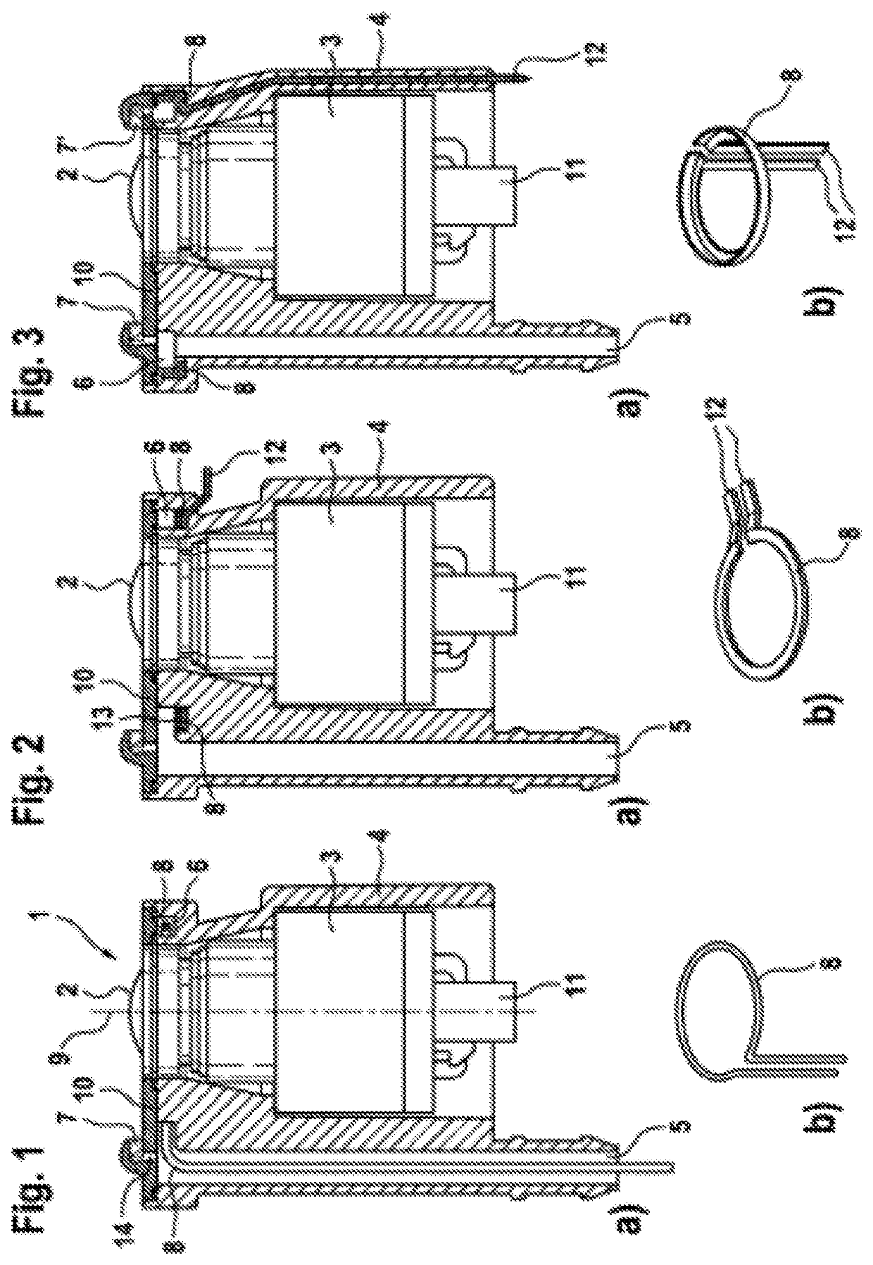
[0023]FIG. 1 depicts the cleaning device 1 according to the invention. An optical or optoelectronic device 3 is disposed, preferably detachable and in particular latched, in a housing 4.
[0024]The electrical interface 11 serves to connect device 3 to one or more electrical supply facilities and electronic control units, which are not shown here.
[0025]A fluid, preferably a liquid cleaning agent is conveyed by a conveying means (not shown)—for example a pump—through a tube-like cleaning agent inlet 5 into an annular channel 6 that is formed into housing 4.
[0026]The annular channel 6 is essentially formed by a recess inside housing 4, which extends radially around an optical axis (9) of device 3. It is closed by a cover element 10, which is attached to housing 4 in a sealed and pressure-tight manner, welded in the present exemplary embodiment.
[0027]A nozzle 7 is disposed on the cover element 10 and is hydraulically connected with the annular channel 6 through a borehole 14. When the not...
second embodiment
[0033]FIG. 2 depicts the cleaning device 1 according to the invention. In contrast to the embodiment according to FIG. 1 the heating element 8 is in this instance essentially annular, with a protruding heating element connection 12, stamped out from a sheet metal material. In contrast to the previously described embodiment, the heating element is placed into the recessed annular channel 6 and cast over with a casting compound 13, which isolates it from the wetted part of the annular channel 6. This allows the electrical heating element connection 12 to protrude at any desired and suitable location from the housing 4.
[0034]FIG. 3
third embodiment
[0035]the cleaning device 1 according to the invention is provided with two nozzles 7,7′, which are supplied from the annular channel 6. It is fundamentally possible to use three or more nozzles within the scope of an aspect of the invention.
[0036]The heating element 8 is press-formed from a sheet metal material and is provided with a separate heating element connection 12; it is, however, embedded directly inside housing 4, for example injection-molded, in contrast to the embodiment according to FIG. 2. To improve the heat transfer from the heating element 8 to the inner space of the annular channel 6 as well as to the adjoining area of housing 4 and to the device 3 disposed therein, the heating element 8 is shown to have an L-shaped cross-section.
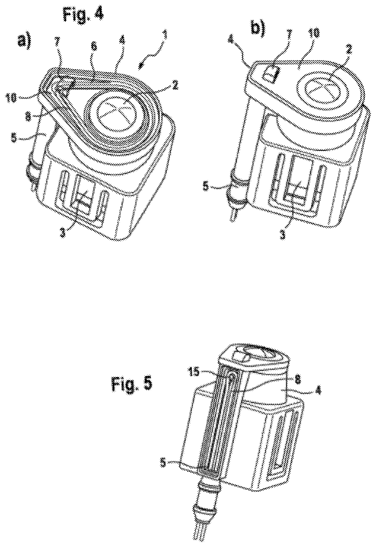
[0037]FIG. 4
[0038]The FIG. 4 depicts the embodiment according to FIG. 1 in three-dimensional view. In this instance the cover element in view a) is shown transparent so as to clearly show the internal design of the annular channel 6 and t...
PUM
| Property | Measurement | Unit |
|---|---|---|
| transparent | aaaaa | aaaaa |
| area | aaaaa | aaaaa |
| metallic | aaaaa | aaaaa |
Abstract
Description
Claims
Application Information
 - R&D
- Intellectual Property
- Life Sciences
- Materials
- Tech Scout
- Unparalleled Data Quality
- Higher Quality Content
- 60% Fewer Hallucinations
Browse by: Latest US Patents, China's latest patents, Technical Efficacy Thesaurus, Application Domain, Technology Topic, Popular Technical Reports.
© 2025 PatSnap. All rights reserved.Legal|Privacy policy|Modern Slavery Act Transparency Statement|Sitemap|About US| Contact US: help@patsnap.com


