Ophthalmic lens identification using ultrasound

Inactive Publication Date: 2020-05-21
JOHNSON & JOHNSON VISION CARE INC
View PDF0 Cites 1 Cited by
  • Summary
  • Abstract
  • Description
  • Claims
  • Application Information

AI Technical Summary

Benefits of technology

[0009]Lens-to-lens communication may take place wirelessly. There are at least three approaches to communicate lens-to-lens: photonic (light), radio frequency (RF) and ultrasound communication. Communication using light is difficult as the power consumption associated with generating photonic signals sufficiently powerful to overcome ambient interference may be prohibitive for the lens power source. RF signal generation may be possible but challenging. Higher RF frequency signals are required to operate with antennas that are sized to fit within a typical contact lens application. Generation of higher frequency signals typically require more power due to less effici

Problems solved by technology

Communication using light is difficult as the power consumption associated with generating photonic signals sufficiently powerful to overcome ambient interference may be prohibiti

Method used


Image

  • Ophthalmic lens identification using ultrasound
  • Ophthalmic lens identification using ultrasound
  • Ophthalmic lens identification using ultrasound

Examples


Example

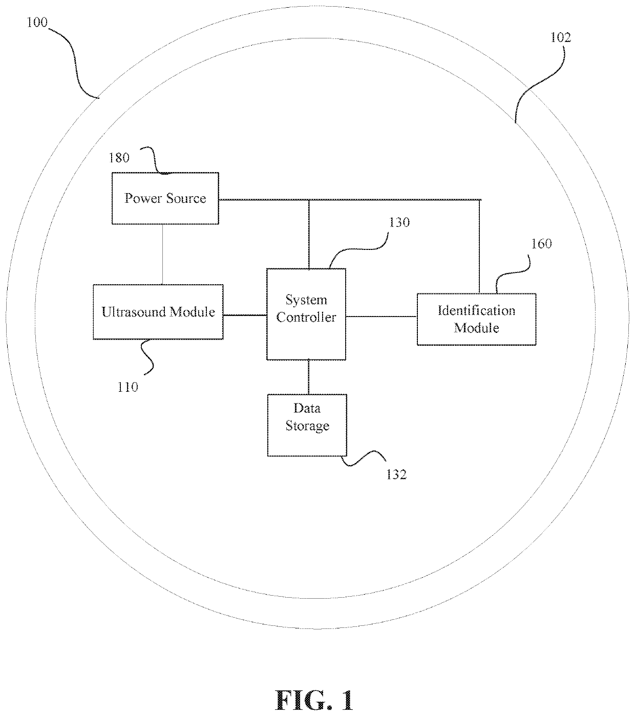
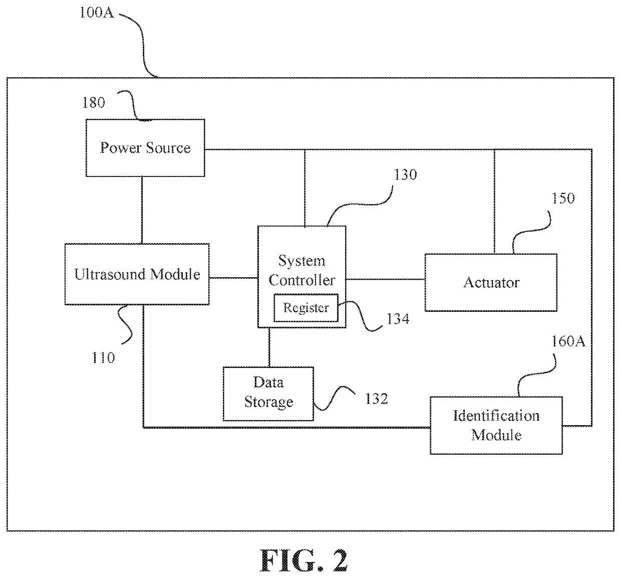
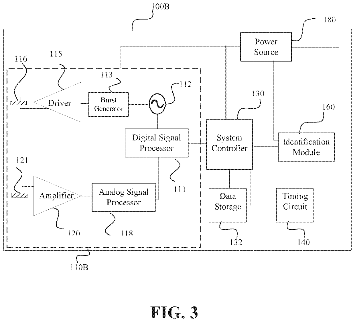
[0034]Conventional contact lenses are polymeric structures with specific shapes to correct various vision problems as briefly set forth above. To achieve enhanced functionality, various circuits and components may be integrated into these polymeric structures. For example, control circuits, microprocessors, communication devices, power supplies, sensors, ultrasound modules, and miniature antennas may be integrated into contact lenses via custom-built optoelectronic components to not only correct vision, but to enhance vision as well as provide additional functionality as is explained herein. Electronic and / or powered ophthalmic lenses may be designed to provide enhanced vision via zoom-in and zoom-out capabilities, or just simply modifying the refractive capabilities of the lenses. Electronic and / or powered ophthalmic lenses may be designed to enhance color and resolution. In addition, ultrasound modules built into the lenses may be utilized to provide / receive an identification tag ...


PUM


Abstract

An ophthalmic lens having an electronic system is described herein for providing an identification in response to a signal or inquiry and/or receiving an identification tag. The ophthalmic lenses include at least one ultrasound module having at least one transducer such as a transmit transducer or a piezoelectric transducer. The ophthalmic lens further includes an identification module for generating an identification in response to a signal and powering the ultrasound module to propagate at least one sound pressure wave embodying the identification. In at least one embodiment, the identification data is encoded after manufacture of the device. The ophthalmic lens may be a contact lens or an intraocular lens.

Description

BACKGROUND OF THE INVENTION1. Field of the Invention[0001]The present invention relates to a powered or electronic ophthalmic lens, and more particularly, to a powered or electronic ophthalmic lens having an identification module to provide an identification in response to an inquiry and / or be assigned an identification number by an external device.2. Discussion of the Related Art[0002]As electronic devices continue to be miniaturized, it is becoming increasingly more likely to create wearable or embeddable microelectronic devices for a variety of uses. Such uses may include monitoring aspects of body chemistry, administering controlled dosages of medications or therapeutic agents via various mechanisms, including automatically, in response to measurements, or in response to external control signals, and augmenting the performance of organs or tissues. Examples of such devices include glucose infusion pumps, pacemakers, defibrillators, ventricular assist devices and neurostimulators...

Claims


Application Information

Patent Timeline
IPC IPC(8): G02C7/02G02C7/08H01L27/24H04B11/00
CPCG02C7/04G02C7/024G02C7/083G02C7/022H01L27/24H04B11/00G02C11/10H10B63/00
Inventor LANGFORD, DONALD SCOTTTONER, ADAM
Owner JOHNSON & JOHNSON VISION CARE INC
Why Eureka
Try Eureka