Pneumatic propulsion system for high capacity transport of passengers and/or cargo

Active Publication Date: 2020-05-28
AEROM REPRESENTACOES E PARTICIPACOES LTDA
View PDF0 Cites 2 Cited by
  • Summary
  • Abstract
  • Description
  • Claims
  • Application Information

AI Technical Summary

Problems solved by technology

Nevertheless, none of the state of the art documents provides a pneumatic transport system for passengers and/or cargo with high capacity, that is, presenting arrangements of equipment for m

Method used


Image

  • Pneumatic propulsion system for high capacity transport of passengers and/or cargo
  • Pneumatic propulsion system for high capacity transport of passengers and/or cargo
  • Pneumatic propulsion system for high capacity transport of passengers and/or cargo

Examples


Example

[0030]The improvement in high capacity pneumatic propulsion system for transport of passengers and / or cargo of the present invention is now described in detail on the basis of the enclosed figures listed below:

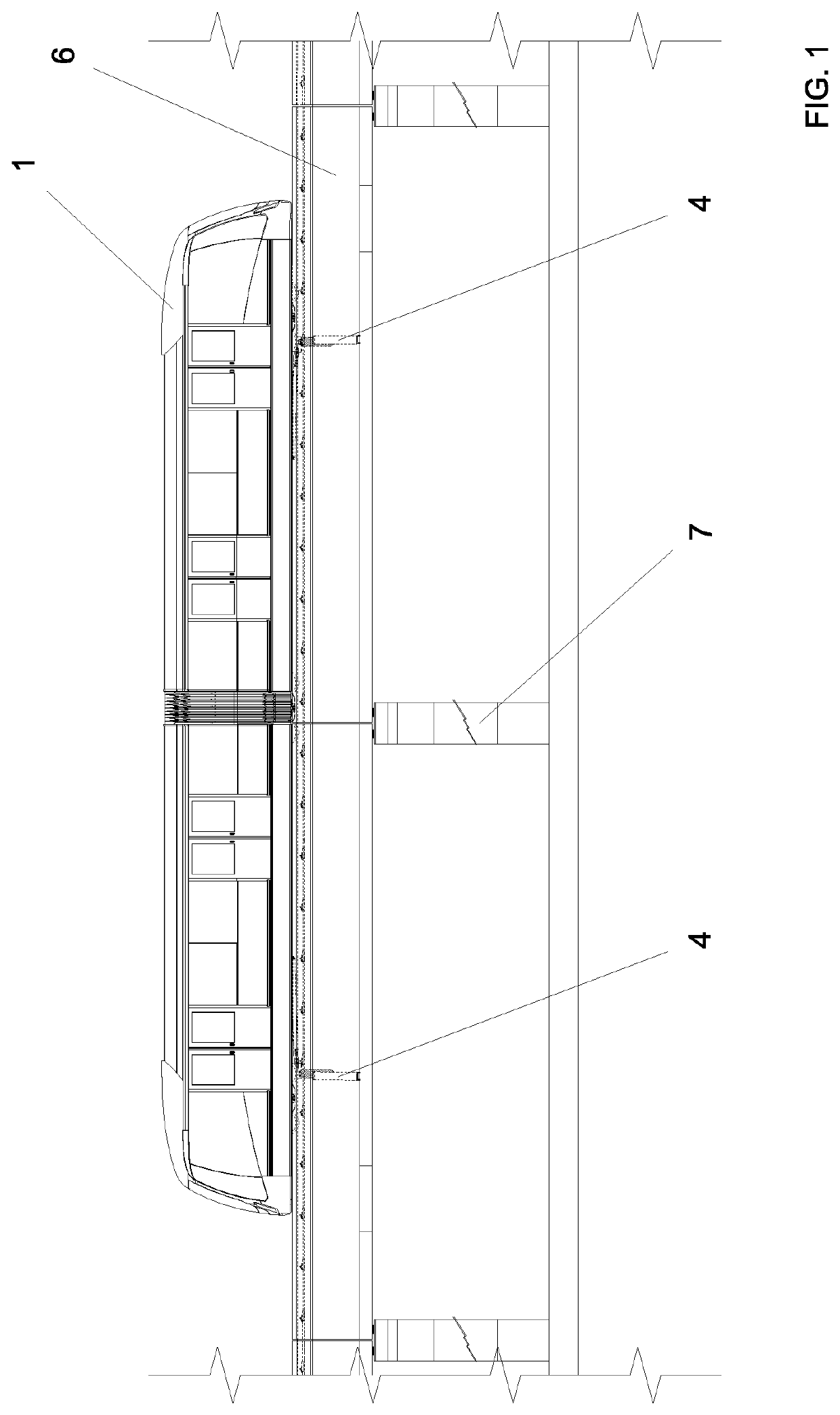
[0031]FIG. 1—side view of the vehicle on the elevated guideway;

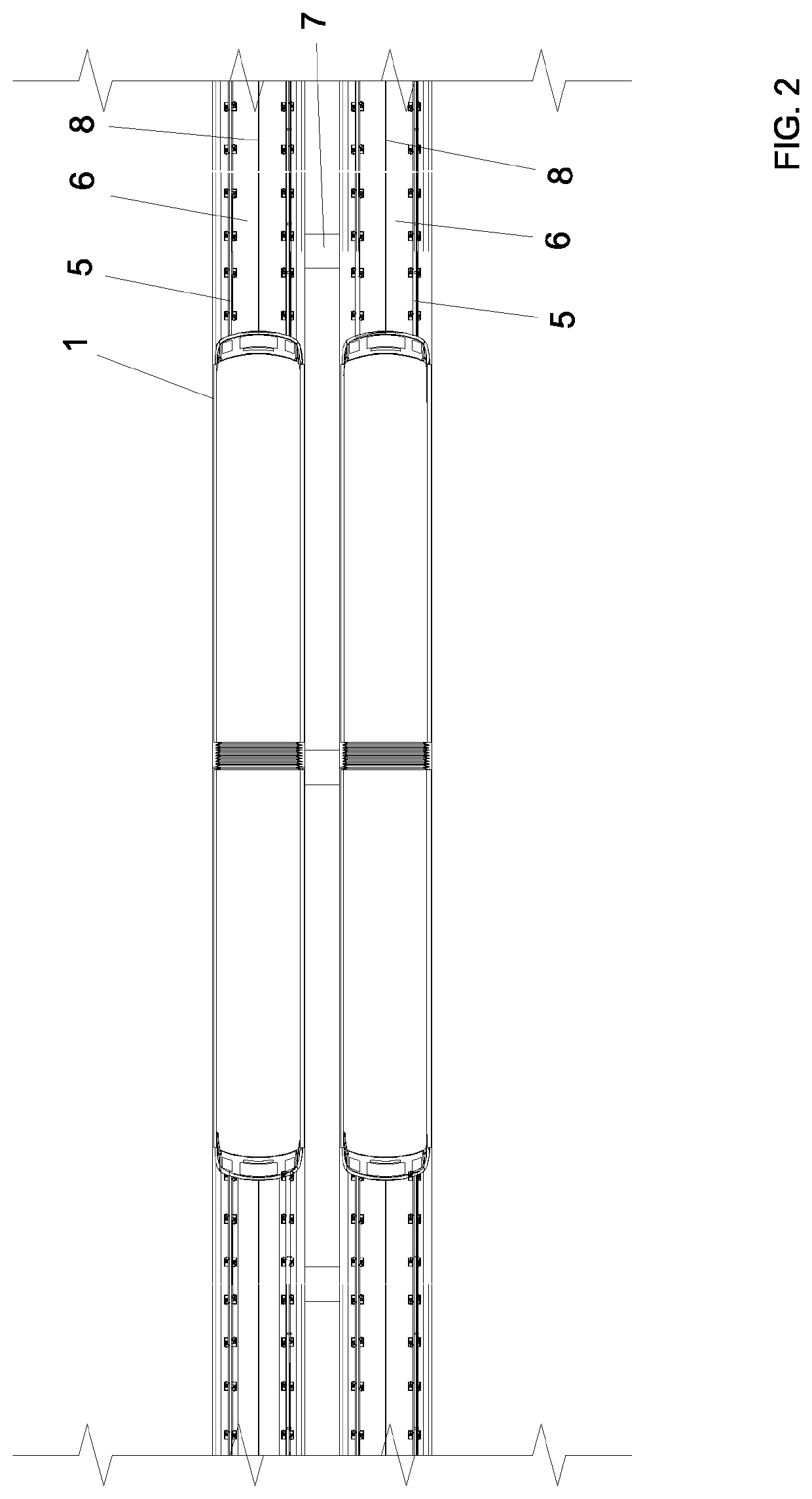
[0032]FIG. 2—top view of the vehicle on the elevated guideway;

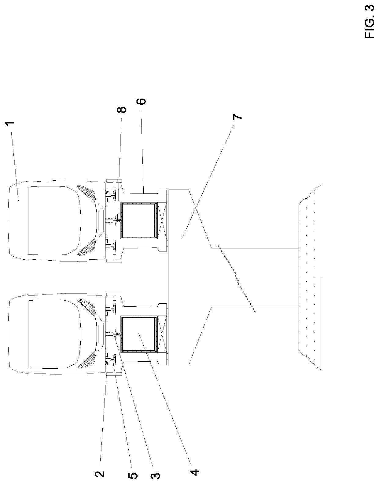
[0033]FIG. 3—front view of the vehicle on the elevated guideway;

[0034]FIG. 4—top view of a passenger station at the level of the technical pavement;

[0035]FIG. 5—front view of the passenger station;

[0036]FIG. 6—side view of the passenger station;

[0037]FIG. 7—perspective view of the power propulsion unit coupled to the guideway;

[0038]FIG. 8—exploded perspective of power propulsion unit and of guideway;

[0039]FIG. 9—diagram of a first arrangement of the propulsion equipment;

[0040]FIG. 10—diagram of a second arrangement of the propulsion equipment;

[0041]FIG. 11—diagram of a third arrangement of the propulsion equipment;

[0042]FIG. 12—diagram of a fourth arrang...


PUM


Abstract

A propulsion system is composed of vehicles with four wheels having one of the axles connected to a pylon attached to the propulsion plate. The vehicles move over rails of elevated guideways supported by pillars. The top of the elevated guideways has longitudinal slots for allowing passage of pylons of propulsion plates. The elevated guideway is dual and has two power propulsion units for propulsion operation in a push and/or pull mode, one for each elevated guideway. The power propulsion units are installed inside the machine rooms under the pavement of the sob passenger stations supported on pillars. The power propulsion units are connected to the elevated guideways by means of connection ducts. Secondary propulsion ducts are disposed in parallel with the propulsion duct and integrated with its respective flow direction valve which allows that the air flow generated by the power propulsion unit is discharged in the propulsion duct in two distinct positions. The pneumatic propulsion arrangement is completed by isolation valve sets of the guideway section, atmospheric valve sets, set of four air flow control valves mounted in the connection ducts of the power propulsion units and flow direction valves.

Description

INTRODUCTION[0001]The present invention relates to improvement developed in pneumatic propulsion system for transport of passengers and / or cargo, which integration of equipment and arrangements render it high capacity and maximum operational flexibility.STATE OF THE ART[0002]Patent documents PI 7703372-8, PI 79062555, PI 8301706-2, PI 8503504-1, PI 9502056-0, PI 9814160-0, PI 9912112-3, PI 0805188-7 and PI 0901119-6 disclose a pneumatic transport system which is composed of light vehicles preferably provided with trucks, containing four metallic wheels each, at least one of the axles being connected to a pylon bolted to a propulsion plate, which is responsible for the conversion of the fluid thrust into mechanical work for moving the vehicles over railway rails seated on a special elevated guideway.[0003]Mounted on vertical pillars, the elevated guideway, besides the classic function of sustaining and directing the vehicles, is also featured by its propulsion duct comprising a devic...

Claims


Application Information

Patent Timeline
IPC IPC(8): B61B13/12
CPCB61B13/122B61B5/02B61B1/00
Inventor COESTER, MARCUSABS DA CRUZ, DIEGOCOESTER, OSCAR HANS WOLFGANG
Owner AEROM REPRESENTACOES E PARTICIPACOES LTDA
Why Eureka
Try Eureka