
Melt blown nonwoven fabric, laminate using same, melt blown nonwoven fabric production method and melt blowing apparatus

Active Publication Date: 2020-06-04
KURARAY CO LTD
View PDF0 Cites 0 Cited by
  • Summary
  • Abstract
  • Description
  • Claims
  • Application Information

AI Technical Summary

Benefits of technology

The invention relates to a special type of fabric that can be used to make items like clothing and other items. The fabric has a soft texture and is very stable at high temperatures. The invention also provides a method and apparatus for making this fabric using a specific heating system and air gap. The result is a highly specialized fabric that is soft and can withstand high temperatures.

Problems solved by technology

However, Patent Document 1 requires the web to be subjected to an additional heat treatment process, so that the resultant nonwoven fabric has hard texture due to heating of the web itself.
Further, the MB nonwoven fabric produced by such a production process inevitably has a lower strength than those of typical MB nonwoven fabrics made of easily-crystallized polymers.
Further, the inventors of the present invention identified a new problem that in such a case, soft texture of MB nonwoven fabrics is deteriorated.

Method used


Image

  • Melt blown nonwoven fabric, laminate using same, melt blown nonwoven fabric production method and melt blowing apparatus
  • Melt blown nonwoven fabric, laminate using same, melt blown nonwoven fabric production method and melt blowing apparatus
  • Melt blown nonwoven fabric, laminate using same, melt blown nonwoven fabric production method and melt blowing apparatus

Examples


example 2

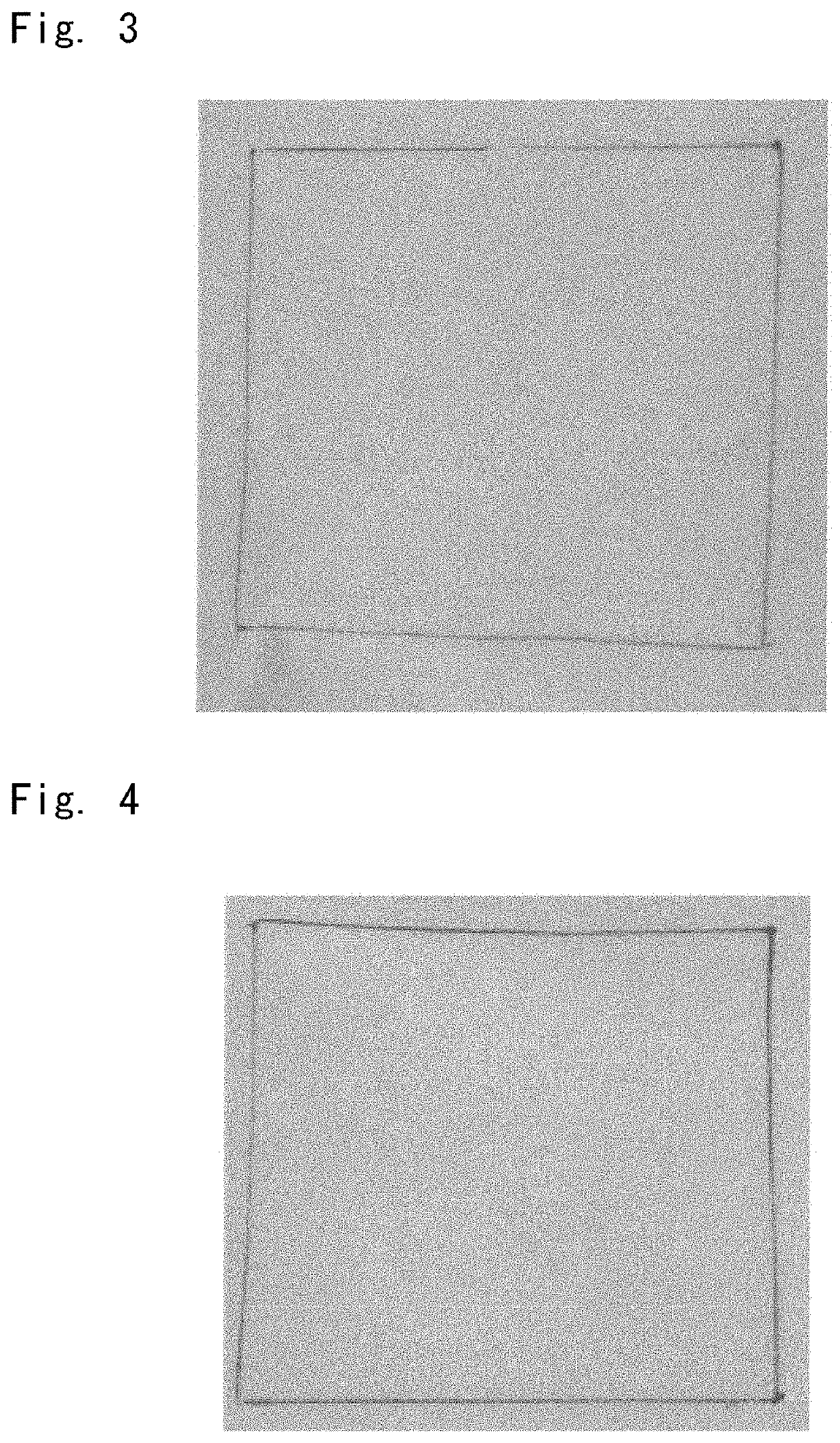
[0129]Example 2 was carried out in the same manner as that of Example 1, except that the heated air flow had a blowing temperature of 180° C. In this Example, the temperature 5 cm below the nozzle was 141.1° C., and the temperature of the fiber materials measured 10 cm below the spinning nozzle was 110.3° C. FIG. 4 shows the obtained MB nonwoven fabric after being subjected to heating at 200° C.

example 3

[0130]Example 3 was carried out in the same manner as that of Example 1, except that the heat-insulating cover provided below the nozzle had a length of 15.0 cm, that the air gap zone had a length of 5.0 cm, and that the heated air flow had a blowing temperature of 300° C. In this Example, the temperature 5 cm below the nozzle was 142.0° C., and the temperature of the fiber materials measured 10 cm below the spinning nozzle was 130.7° C.

example 4

[0131]Example 4 was carried out in the same manner as that of Example 1, except that the heat-insulating cover provided below the nozzle had a length of 15.0 cm and that the air gap zone had a length of 8.0 cm. In this Example, the temperature 5 cm below the nozzle was 145.2° C., and the temperature of the fiber materials measured 10 cm below the spinning nozzle was 137.6° C.


PUM

PropertyMeasurementUnit
Temperatureaaaaaaaaaa
Lengthaaaaaaaaaa

Abstract

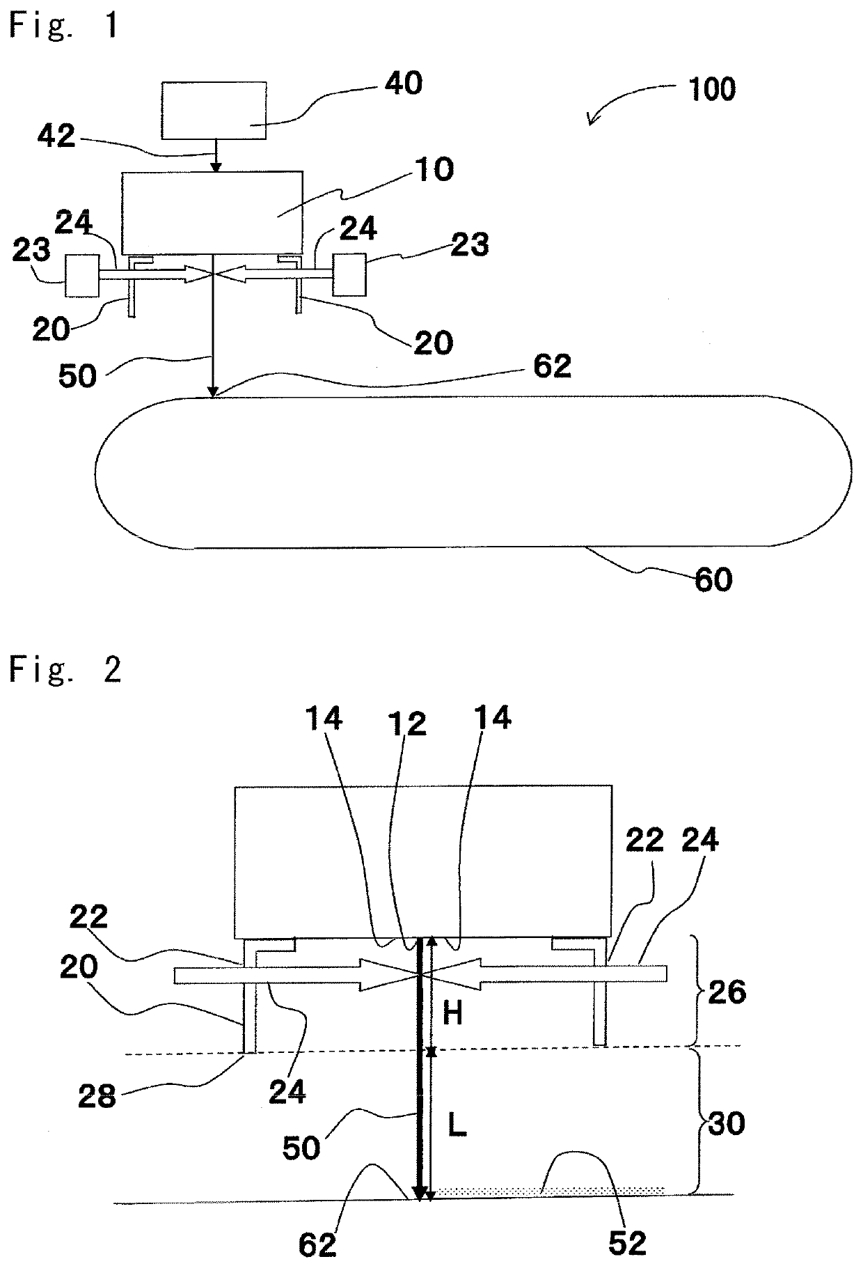
Provided are a melt blown (MB) nonwoven fabric, a laminate using the same, a method of producing a melt blown nonwoven fabric as well as a melt blowing apparatus. A melt blowing apparatus 100 includes a die 10 configured to discharge a resin melt 42 with an accompanying jet to give fiber materials, a hollow cover 20, and a collector 60. The fiber materials 50 from the die 10 are heated to a temperature equal to or higher than a crystallization temperature of crystalline thermoplastic resin inside the hollow cover 20 and collected on a collecting surface 62 of the collector 60. The hollow cover 20 and the collector 60 are separated by a distance of 5 cm or longer between a lower edge 28 of the hollow cover 20 and the collecting surface 62 in a line extending downwardly from the nozzle holes 12 in a vertical direction.

Description

CROSS REFERENCE TO THE RELATED APPLICATION[0001]This application is a continuation application, under 35 U.S.C § 111(a) of international application No. PCT / JP2018 / 028417, filed Jul. 30, 2018, which claims priority to Japanese patent application No. 2017-155193, filed Aug. 10, 2017, the entire disclosures of which are herein incorporated by reference as a part of this application.BACKGROUND OF THE INVENTIONField of the Invention[0002]The present invention relates to a melt blown nonwoven fabric having improved thermostability and soft texture, to a laminate using the same, to a method of producing a melt blown nonwoven fabric as well as to a melt blowing apparatus.Description of Related Art[0003]Although polyethylene terephthalate (PET) resin has been utilized in various forms as nonwoven fabrics because of their high versatility, their application is little expanded to be used as melt blown (MB) nonwoven fabrics. One of the reasons is that PET has a lower crystallization speed than...

Claims


Application Information

Patent Timeline
IPC IPC(8): B32B5/26D01D5/08D04H3/011D04H3/16D01D5/092D01D13/00B32B5/02B32B37/26B32B37/04
CPCB32B2367/00D01D5/08B32B2605/00B32B5/022B32B37/26D04H3/011D01D5/092B32B2307/724D01D13/00B32B37/04D04H3/16B32B2307/102B32B2307/704B32B5/26B32B2305/18D04H1/435D01D5/0985D01D5/084
Inventor OKAMOTO, TETSUYASHIROTANI, YASUHIRO
Owner KURARAY CO LTD
Learn More