System and Method for Improving Travel Across Joints in a Track for a Linear Motion System

a technology of linear motion and motion control system, which is applied in the direction of electric vehicle charging technology, climate sustainability, transportation and packaging, etc., can solve the problems of reducing the communication bandwidth required for position information, introducing position determination errors, and not being practicable to transmit position feedback information back, so as to reduce jitter or torque pulsation

Active Publication Date: 2020-06-04
ROCKWELL AUTOMATION TECH
View PDF0 Cites 8 Cited by
  • Summary
  • Abstract
  • Description
  • Claims
  • Application Information

AI Technical Summary

Benefits of technology

[0010]Having knowledge of the position for the mover determined both locally and by the adjacent controller to which the mover is transitioning allows the local controller to determine the compensated position value. The compensated position value may be, for example, an average of the local position value and shared position value. Optionally, the local controller may monitor the position of the mover as it transitions between the two track segments and utilize a moving, weighted average of the two values. The local controller places a greater weight on the position value determined by the respective controller on which a greater portion of the mover resides. Utilizing either the average or the weighted average of the position value reduces the effects of a difference in the measured value of the position on each mover.
[0011]Each controller utilizes the compensated value of the position value as determined on that controller to control operation of the mover while it is present on the corresponding track segment. The compensated value of the position reduces or eliminates a step change in the position value as the move transitions between segments. Instead the compensated value of the position gradually transitions from the local measured value of position in the first controller to a shared value that is the same for both controllers when the mover is at the midpoint between the two track segments. The second controller assumes control of the mover with a position value at the shared value and gradually transitions to the local measured value of position in the second controller. The gradual transition between local measured values reduces jitter or torque pulsations occurring on the mover during the transition between track segments.
[0013]According to another embodiment of the invention, a method for improving motion of movers across junctions in a linear drive system is disclosed. A first position feedback signal is received with a first controller from a first position sensor on a first track segment. The first position feedback signal corresponds to a position of a mover traveling across a junction between the first track segment and a second track segment in the linear drive system. A first measured position of the mover is determined with the first controller as a function of the first position feedback signal. A second position feedback signal is received with a second controller from a second position sensor on the second track segment. A second measured position of the mover is determined with the second controller as a function of the second position feedback signal. The first measured position is transmitted from the first controller to the second controller, and the second measured position is transmitted from the second controller to the first controller. A first compensated position of the mover is determined with the first controller as a function of the first measured position and the second measured position, and a second compensated position of the mover is determined with the second controller as a function of the first measured position and the second measured position. Operation of the mover on the first track segment is controlled with the first controller as a function of the first compensated position, and operation of the mover is controlled on the second track segment with the second controller as a function of the second compensated position.
[0014]According to still another embodiment of the invention, a method for improving motion of movers across junctions in a linear drive system is disclosed. A first position feedback signal is received with a first controller from a first position sensor on a first track segment. The first position feedback signal corresponds to a position of a mover traveling across a junction between the first track segment and a second track segment in the linear drive system. A first measured position of the mover is determined with the first controller as a function of the first position feedback signal. A second position feedback signal is received with a second controller from a second position sensor on the second track segment. A second measured position of the mover is determined with the second controller as a function of the second position feedback signal. A first compensated position is transmitted from the first controller to the second controller, and a second compensated position is transmitted from the second controller to the first controller. The first compensated position of the mover is determined with the first controller as a function of the first measured position and the second compensated position, and the second compensated position of the mover is determined with the second controller as a function of the first compensated position and the second measured position. Operation of the mover on the first track segment is controlled with the first controller as a function of the first compensated position, and operation of the mover on the second track segment is controlled with the second controller as a function of the second compensated position.

Problems solved by technology

Due to the high rate of travel of each mover, the number of movers present in the system, and the number of track segments present in the system, it is typically not practical to transmit position feedback information back to a central controller to perform real-time monitoring of the position for each mover and, in turn, transmit this position information back to the controller for each track segment to control operation of the movers present on the track segment.
The segment controller may periodically transmit position information for each mover back to a central controller which monitors the location of the movers, however, this information is sent at a lower periodic rate than required to control operation of each mover, reducing the communication bandwidth required for position information.
A gap between the two track segments, however, introduces error in the position determination.
In addition, variations in the placement of the position sensors during manufacturing of each track segment or variations in the signals output from the position sensors due to the tolerances of the sensor itself, provide an additional source of potential error in the position feedback signals between adjacent segments.
Still another potential source of error arises in the control of the movers themselves.

Method used


Image

  • System and Method for Improving Travel Across Joints in a Track for a Linear Motion System
  • System and Method for Improving Travel Across Joints in a Track for a Linear Motion System
  • System and Method for Improving Travel Across Joints in a Track for a Linear Motion System

Examples


Embodiment Construction

[0032]The various features and advantageous details of the subject matter disclosed herein are explained more fully with reference to the non-limiting embodiments described in detail in the following description.

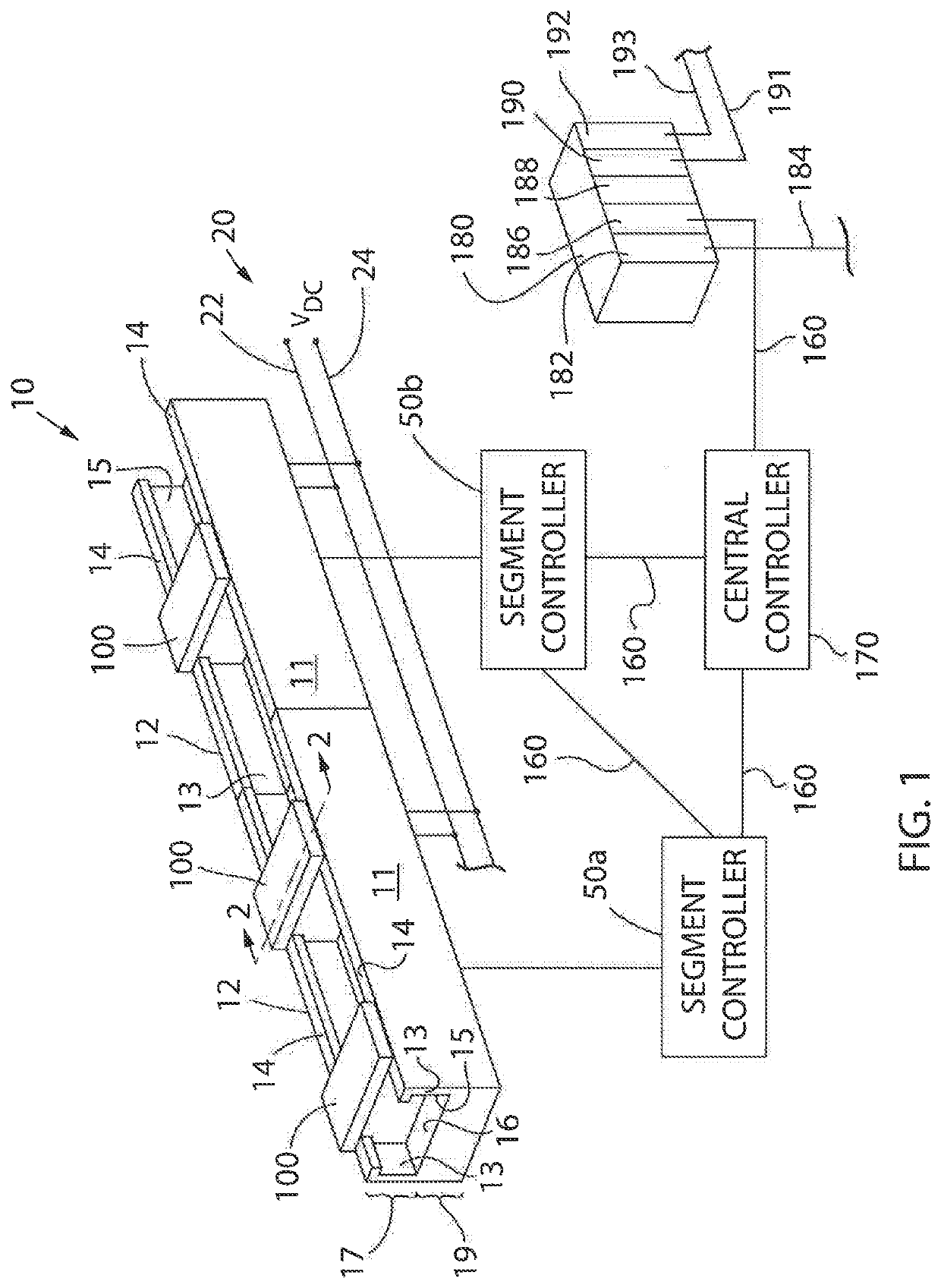
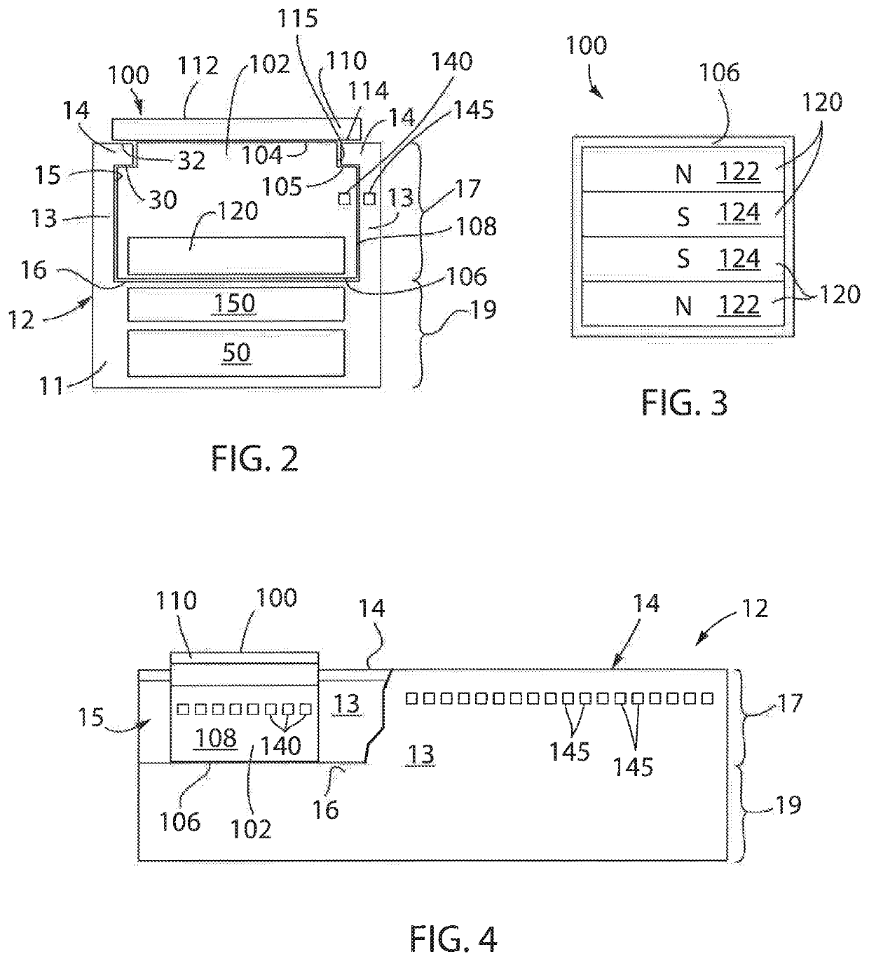
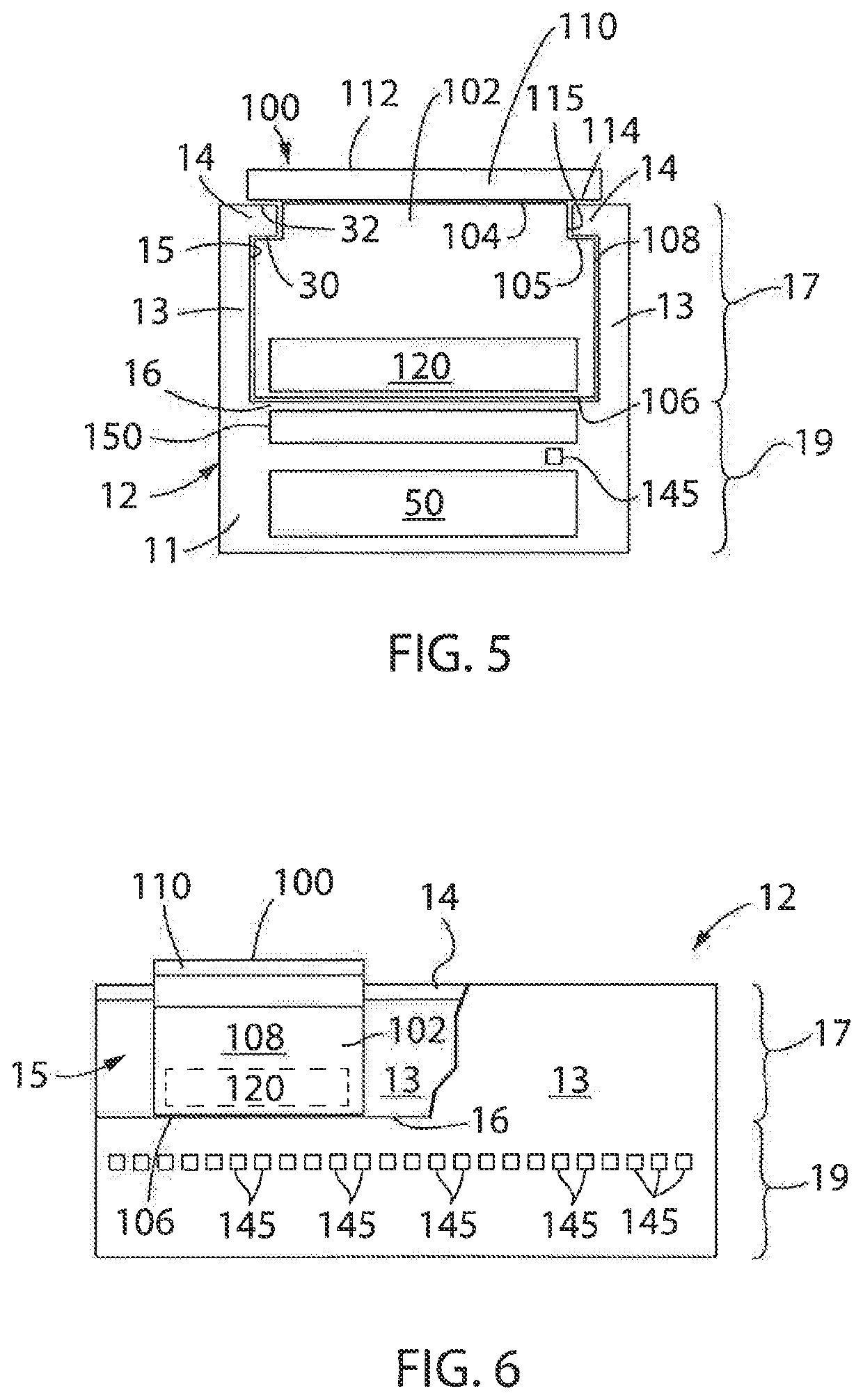
[0033]Turning initially to FIGS. 1-4, an exemplary transport system for moving articles or products includes a track 10 made up of multiple segments 12. According to the illustrated embodiment, multiple segments 12 are joined end-to-end to define the overall track configuration. The illustrated segments 12 are both straight segments having generally the same length. It is understood that track segments of various sizes, lengths, and shapes may be connected together to form the track 10 without deviating from the scope of the invention. Track segments 12 may be joined to form a generally closed loop supporting a set of movers 100 movable along the track 10. The track 10 is illustrated in a horizontal plane. For convenience, the horizontal orientation of the track 10 shown in ...


PUM


Abstract

A system for determining the position of a mover as the mover transitions between segments along a track includes a first controller on a first track segment and a second controller on a second track segment. The first and second track segments are adjacent to each other and a junction is located between the two segments. The first and second controllers are in communication with each other and share a locally determined position value with the other controller. Each controller determines a compensated position value as a function of both a locally determined position value and the shared position value received from the other controller. Each controller utilizes the compensated value of the position value as determined on that controller to control operation of the mover while it is present on the corresponding track segment.

Description

BACKGROUND INFORMATION[0001]The present invention relates to motion control systems and, more specifically, to improved control of movers traveling between track segments in a linear drive system.[0002]Motion control systems utilizing movers and linear drives can he used in a wide variety of processes (e.g. packaging, manufacturing, and machining) and can provide an advantage over conventional conveyor belt systems with enhanced flexibility, extremely high-speed movement, and mechanical simplicity. The motion control system includes a set of independently controlled “movers” each supported on a track for motion along the track. The track is made up of a number of track segments that, in turn, hold individually controllable electric coils. Successive activation of the coils establishes a moving electromagnetic field that interacts with the movers and causes the mover to travel along the track.[0003]Each of the movers may be independently moved and positioned along the track in respon...

Claims


Application Information

Patent Timeline
Patent Type & Authority Applications(United States)
IPC IPC(8): B60L13/10B60L15/00
CPCB60L2200/26B60L13/10B60L15/005B60L13/03Y02T90/16
Inventor HUANG, YUHONG
Owner ROCKWELL AUTOMATION TECH
Why Eureka
Try Eureka