Bearing housing for a turbomachine, and turbomachine having a bearing housing

a technology for bearing housings and turbomachines, which is applied in the direction of liquid fuel engines, shafts, engine fuctions, etc., can solve the problems of increased wear or even bearing failures, high bearing housing costs, etc., and achieves sufficient lubrication and cooling, the effect of expanding the ambient temperature range for operation, and sufficient cooling of bearings and lubricants

Inactive Publication Date: 2020-06-04
SULZER MANAGEMENT AG
View PDF6 Cites 0 Cited by
  • Summary
  • Abstract
  • Description
  • Claims
  • Application Information

AI Technical Summary

Benefits of technology

[0011]This makes it possible to achieve sufficient cooling of the bearing and the lubricant even at high ambient temperatures and thus to expand the ambient temperature range for the operation of the flow machine. This ensures sufficient lubrication and cooling even at outside air temperatures above 50° C., which can increase the service life of the bearing.
[0012]In a preferred embodiment, the lubricant chamber is filled with the lubricant up to a lubricant level in the operating state and the internal cooling fins extend completely below the lubricant level. As a result, the contribution of the internal cooling fins for heat exchange is particularly effective.
[0013]In a particularly preferred embodiment, the internal cooling fins extend in the direction of the bearing axis. As a result, the production of the bearing housing is particularly simplified.
[0014]Alternatively, it is also possible, that the internal cooling fins extend in the circumferential direction with respect to the bearing axis. This also simplifies the production of the bearing housing.
[0015]In addition, it is also possible, that the internal cooling fins extend spirally with respect to the bearing axis. This results in improved circulation of the lubricant in the lubricant chamber, whereby a more effective heat exchange can be achieved.
[0016]It has also proven to be advantageous if the opening is formed as a slot. This results in an improved supply of lubricant into the bearing chamber. Preferably, the slot extends in the direction of the hearing axis.

Problems solved by technology

It has been determined that, in practice, under certain operating conditions, e.g. high outside air temperatures above 50° C., the cooling techniques mentioned are insufficient and expensive, resulting in an increased wear or even bearing failure or high bearing housing costs.

Method used


Image

  • Bearing housing for a turbomachine, and turbomachine having a bearing housing
  • Bearing housing for a turbomachine, and turbomachine having a bearing housing
  • Bearing housing for a turbomachine, and turbomachine having a bearing housing

Examples


first embodiment

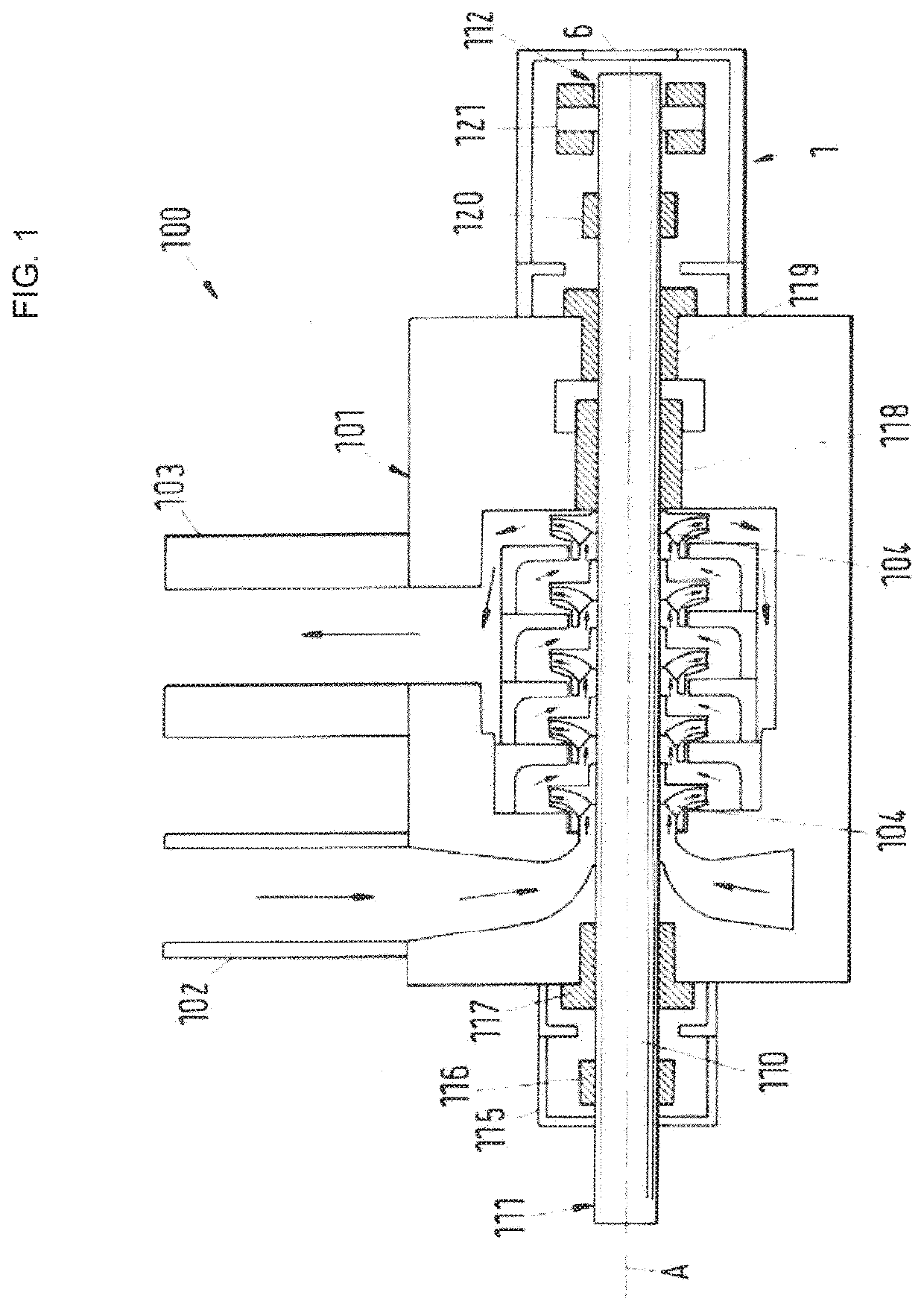
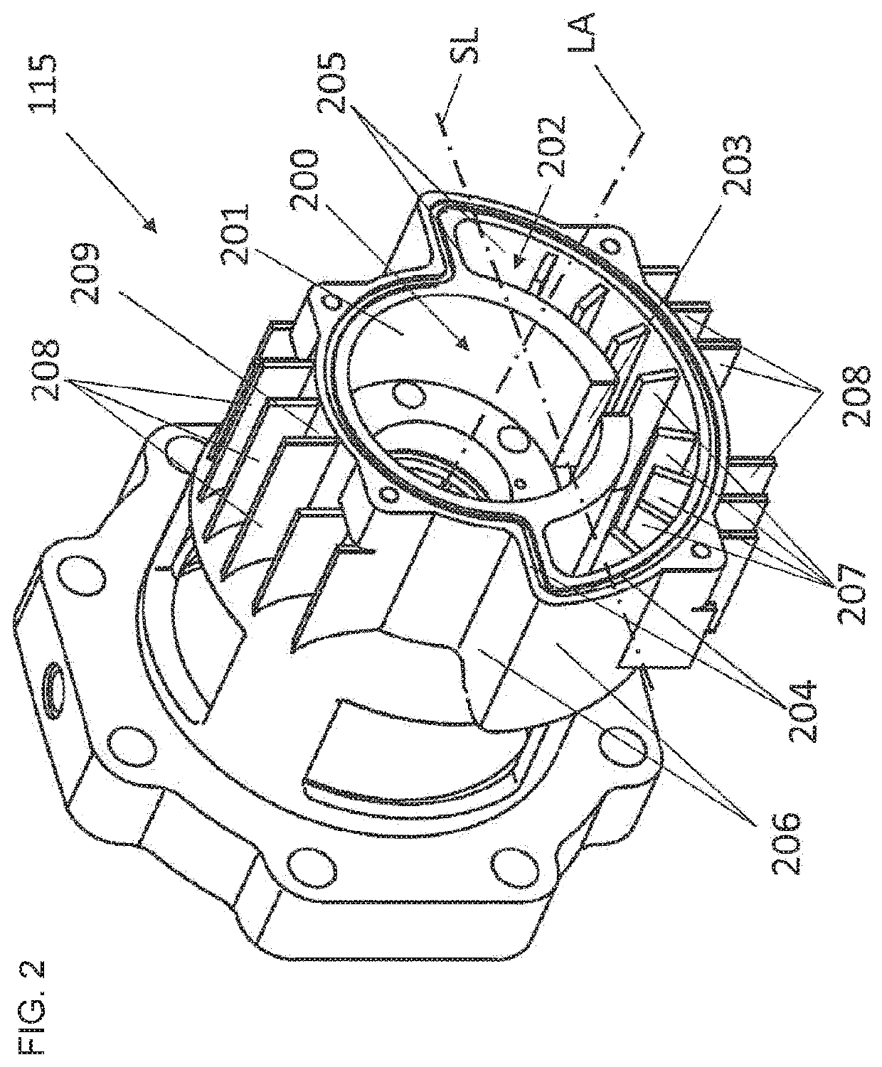
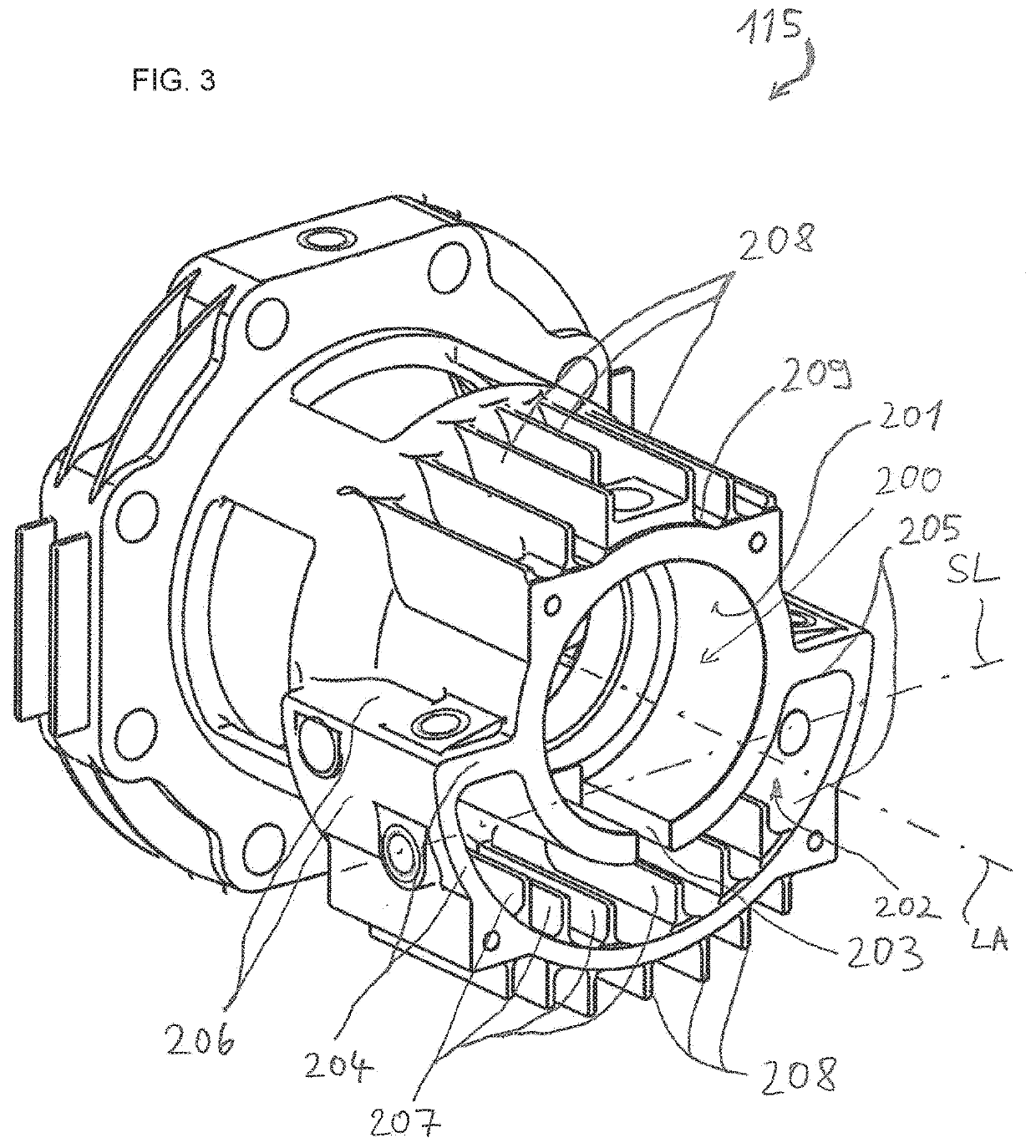
[0037]FIG. 2 shows a perspective view of the bearing housing 115 according to the invention for receiving the drive end 111 of the shaft 110 of the flow machine 100. The hearing housing 115 comprises a hearing axis LA, a bearing chamber 200 with a bearing chamber surface 201 for receiving a bearing (not shown) and a lubricant chamber 202 for receiving a lubricant. In this embodiment, the lubricant chamber 202 encloses the bearing chamber 200 partially tubular, i.e. the lubricant chamber 202 has a U-shaped cross-section. The radially outer wall, which delimits the U-shaped lubricant chamber 202, is essentially designed as a ring segment and is arranged coaxially with the bearing chamber 200. This means that the lubricant chamber 202 surrounds about half of the essentially cylindrical bearing chamber 200 radially on the outside. The lubricant chamber 202 extends below the bearing chamber 200. The lubricant chamber 202 and the bearing chamber 200 are in flow communication via an openin...

second embodiment

[0050]In the second embodiment, a total of six internal cooling fins 207 are provided. The height, the number, the specific design of the internal cooling fins 207 and the distance between adjacent internal cooling fins 207 are optimized under the aspects that sufficient heat dissipation is to be achieved from the lubricant, that the internal cooling fins 207 should be as easy to produce as possible in terms of production technology, in particular in terms of casting technology, and that there is sufficient mixing of the lubricant in the lubricant chamber 202, so that the formation of layers of lubricants of different temperatures in the lubricant chamber 202 is avoided as far as possible.


PUM


Abstract

A bearing housing for a flow machine includes a bearing axis, a bearing chamber, a lubricant chamber and internal cooling fins. The bearing chamber is configured to receive a bearing. The lubricant chamber is configured to receive a lubricant. The lubricant chamber and the bearing chamber are in flow communication via an opening. The lubricant chamber includes a wall portion configured to dissipate heat to the environment, and the wall portion has an inner surface directed towards the lubricant chamber and an outer surface directed towards the environment. The internal cooling fins are arranged at a part of the inner surface.

Description

CROSS-REFERENCE TO RELATED APPLICATION[0001]This application is a U.S. National Stage application of International Application No. PCT / EP2018 / 067231, filed Jun. 27, 2018, which claims priority to European Patent Application No. 17178376.4, filed Jun. 28, 2017, the contents of each of which are hereby incorporated herein by reference.BACKGROUNDField of Invention[0002]The invention relates to a bearing housing for a flow machine. The invention further relates to a flow machine with a bearing housing.Background Information[0003]Conventional flow machines for conveying a fluid, for example centrifugal pumps, compressors, fans, expanders or turbines typically comprise a stationary machine housing that encloses a rotor, e.g. an impeller, which is arranged on a shaft rotating around an axis of the flow machine. The flow machine generally also has at least one bearing unit with a radial and / or axial (thrust) bearing to support the shaft and the rotor. Typically, the bearing unit has a separ...

Claims


Application Information

Patent Timeline
Patent Type & Authority Applications(United States)
IPC IPC(8): F16C37/00F16C33/66
CPCF16C2360/44F16C37/007F16C33/6666F04D1/06F04D29/0473F04D29/061F04D29/5893F05D2260/22141F05D2240/53F05D2260/98
Inventor WILD, ANDREAS
Owner SULZER MANAGEMENT AG
Why Eureka
Try Eureka