Eureka AIR delivers breakthrough ideas for toughest innovation challenges, trusted by R&D personnel around the world.

Vapor chamber sealing method and structre using the same

Active Publication Date: 2020-06-04
KUNSHAN JUZHONG ELECTRONICS
View PDF0 Cites 1 Cited by
  • Summary
  • Abstract
  • Description
  • Claims
  • Application Information

AI Technical Summary

Benefits of technology

The patent aims to provide a method and structure for sealing the edges of a vapor chamber while maintaining the strength of the metal structure. The technical effect of this patent is to improve the reliability and durability of the vapor chamber.

Problems solved by technology

However, the conventional vapor chamber is usually formed on a shell or a plate and mainly comprised of two plates engaged with each other, so that it is necessary to stack the two plates and seal their peripheries by a process such as high temperature sintering or laser welding, but the high temperature of the aforementioned process may cause a deterioration of the metal of the vapor chamber or plates and affect the strength or hardness of the structure of the shell or plate.

Method used


Image

  • Vapor chamber sealing method and structre using the same
  • Vapor chamber sealing method and structre using the same
  • Vapor chamber sealing method and structre using the same

Examples


Embodiment Construction

[0017]The technical contents of this disclosure will become apparent with the detailed description of preferred embodiments accompanied with the illustration of related drawings as follows. It is noteworthy that same numerals are used for representing same respective elements in the drawings.

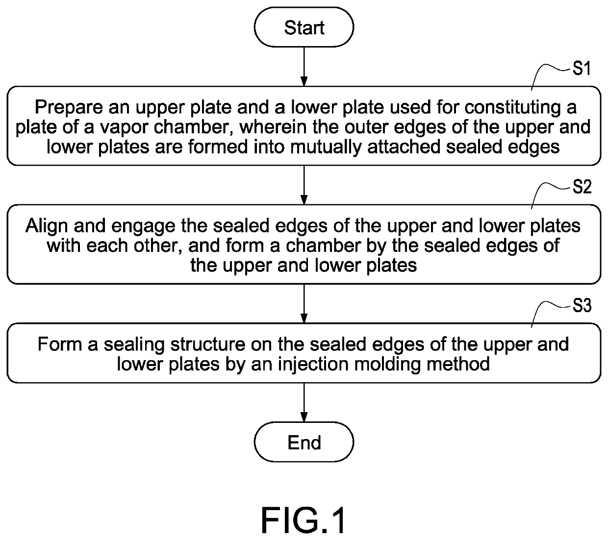
[0018]With reference to FIG. 1 for a flow chart of a vapor chamber sealing method of this disclosure, this disclosure provides a vapor chamber sealing method and its structure capable of sealing the edges of the vapor chamber without requiring the manufacturing process such as high-temperature sintering or laser welding, so as to avoid the issues of deteriorating the metal of the vapor chamber by high temperature and affecting the structural strength or hardness of the vapor chamber.

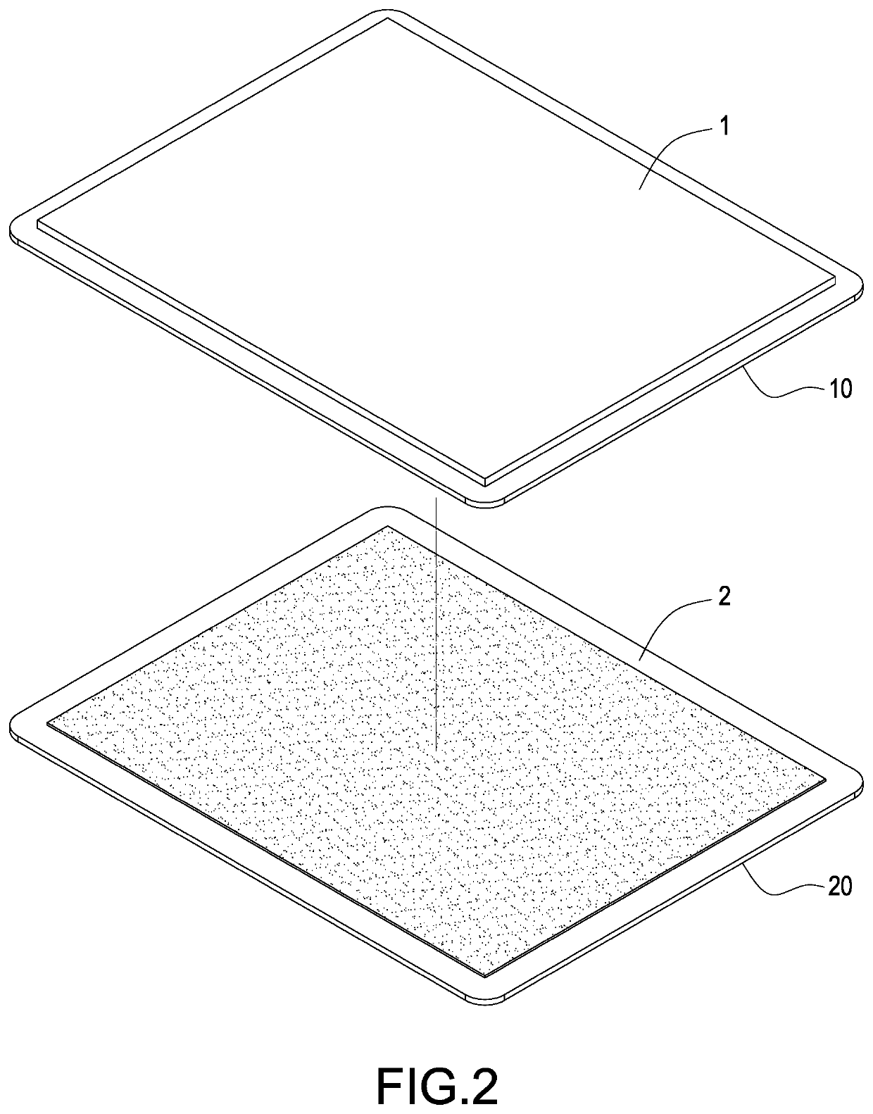
[0019]With reference to FIG. 2 and Step S1 of FIG. 1, an upper plate 1 and a lower plate 2 used for forming a plate of a vapor chamber are prepared, wherein the upper plate 1 has a sealed edge 10 formed at and contin...


PUM


Abstract

Disclosed are a vapor chamber sealing method and a structure using the method. An upper plate and a lower plate used for making a plate of a vapor chamber are prepared, and outer edges of the upper and lower plates are formed into mutually attached sealed edges, and then the sealed edges of the upper and lower plates are aligned and engaged with each other to form a chamber between the upper and lower plates, and a sealing structure is formed and combined with the sealed edges of the upper and lower plates by an injection molding method, and the sealing structure is formed around and combined with the sealed edges of the upper and lower plates.

Description

FIELD OF THE INVENTION[0001]The technical field of this disclosure relates to a flat plate heat pipe, and more particularly to a vapor chamber sealing method and its structure.BACKGROUND OF THE INVENTION[0002]A vapor chamber, also known as a heat conducting plate or a flat plate heat pipe, has functions and operating principle similar to those of heat pipes, and all of the devices have a working fluid sealed into a pipe or plate type chamber and provided for actuating an evaporation-condensation cycle to achieve the effects of a quick heat transfer and a uniform temperature. The vapor chamber has been widely used in various fields of heat dissipation.[0003]However, the conventional vapor chamber is usually formed on a shell or a plate and mainly comprised of two plates engaged with each other, so that it is necessary to stack the two plates and seal their peripheries by a process such as high temperature sintering or laser welding, but the high temperature of the aforementioned proc...

Claims


Application Information

Patent Timeline
IPC IPC(8): F28D15/04F28D15/02
CPCF28D15/0283F28D15/043F28D15/04
Inventor HUANG, YU-PO
Owner KUNSHAN JUZHONG ELECTRONICS
Why Eureka
Eureka Blog
Learn More