
Leak test machine for cylinder head, engine block, or a similar workpiece

a leak testing machine and cylinder head technology, applied in the direction of measurement devices, measurement of fluid loss/gain rate, detection of fluid at leakage point, etc., can solve the problems of critical production-related leakage in the internal chamber of the engine, reduced service life of the engine, and complete or partial failure of the component under operating pressure, so as to increase the degree of automation and reduce maintenance-related downtime

Active Publication Date: 2020-06-25
ELWEMA AUTOMOTIVE
View PDF1 Cites 4 Cited by
  • Summary
  • Abstract
  • Description
  • Claims
  • Application Information

AI Technical Summary

Benefits of technology

The invention is a leak testing machine that can be used for different workpiece types without needing to be retooled. This reduces production complexity and costs. The machine uses a dedicated changeover device that allows for flexibility in testing different components without needing a separate machine for each type. The invention also allows for continuous testing and maintenance without having to stop production. These features make the invention ideal for use in industrial settings.

Problems solved by technology

Only in this way is it possible to ensure proper functioning of the finished engine, because such workpieces or components, generally manufactured from cast blanks, may exhibit critical production-related leaks in their internal chambers, for example pores or cracks caused by casting defects.
A leak in a pressure chamber or internal chamber will cause complete or partial failure of the component under operating pressure.
Depending on the extent of the leak, the service life of the engine would be reduced considerably thereby or the engine may be quickly destroyed.
Subsequent replacement of a leaking cylinder head or engine block would be unacceptable for cost reasons.
The design according to EP 0 122 551 A2 is unsuitable for fully automated manufacture, however.
This is associated with correspondingly complex production, installation, control, maintenance, etc. and large footprints.

Method used


Image

  • Leak test machine for cylinder head, engine block, or a similar workpiece
  • Leak test machine for cylinder head, engine block, or a similar workpiece
  • Leak test machine for cylinder head, engine block, or a similar workpiece

Examples


Embodiment Construction

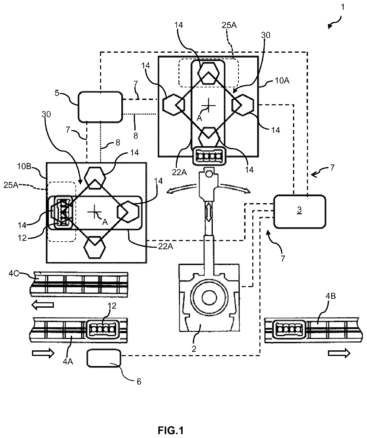
[0062]FIG. 1 shows a system, denoted overall with reference sign 1, with an industrial robot 2 controlled via a system controller 3. The industrial robot 2 is connected to this end via a field bus or industrial bus 7 to the system controller 3, for transmission of control and information signals. The system 1 serves in fully automated tightness testing of workpieces, in FIG. 1 for example of engine blocks 12.

[0063]To this end, the industrial robot 2 removes the engine blocks 12 individually from a conveying path 4A arriving from the upstream stages of a production line and passes them to one of a number of leak testing machines 10A, 10B (two shown here, merely by way of example). The leak testing machines 10A, 10B each have a workpiece holding device 22A in the working zone of the industrial robot 2, so that they can be loaded by the latter with a workpiece. The workpiece holding device 22A brings the engine block 12 suitably into a test position 25A. Each leak testing machine 10A, ...


PUM


Abstract

A flexible leak testing machine for tightness testing of a cylinder head, an engine block or similar workpiece has at least one sealing plate, a machine frame with at least one workpiece holding device for the workpiece and an adjusting device with a first drive for bringing together the workpiece and the sealing plate into a test position. The leak testing machine is flexibly usable in that it includes a changeover device for sealing plates. The changeover device has an adjustable holding arrangement on the machine frame, with sealing plate holders and an associated drive for sealing plate changeover.

Description

CROSS-REFERENCE TO RELATED APPLICATIONS[0001]This application is a Section 371 of International Application No. PCT / EP2016 / 081532, filed Dec. 16, 2016, which was published in the German language on June 22 under International Publication No. WO 2017 / 103176 A1, which claims priority under 35 U.S.C. § 119(b) to German Application No. 20 2015 106 873.5, filed Dec. 16, 2015, the disclosures of which are incorporated herein by reference in their entirety.BACKGROUND OF THE INVENTION[0002]The invention relates in general to a leak testing machine and a system for tightness testing of a cylinder head, an engine block or a comparable industrially produced, technical workpiece with at least one internal chamber to be tested for tightness. The invention further relates to the use thereof in tightness testing of industrial components and to a method for industrial tightness testing, in particular of metal workpieces made from cast blanks. The terms tightness testing and leak testing are here us...

Claims


Application Information

Patent Timeline
Patent Type & Authority Applications(United States)
IPC IPC(8): G01M3/32G01M3/04
CPCG01M3/329G01M3/04G01M3/025G01M15/04
Inventor ALVAREZ, ANTONIOILG, EBERHARD
Owner ELWEMA AUTOMOTIVE
Learn More