MEMS microphone

a microphone and microphone technology, applied in the field of acousticelectronics, can solve the problems of reducing the vibration sensitivity of the vibrating diaphragm, affecting the performance of the microphone, and high noise, and achieve the effect of reducing the noise of the microphone and acoustic resistan

Inactive Publication Date: 2020-06-25
WEIFANG GOERTEK MICROELECTRONICS CO LTD
View PDF4 Cites 8 Cited by
  • Summary
  • Abstract
  • Description
  • Claims
  • Application Information

AI Technical Summary

Benefits of technology

[0024]According to the MEMS microphone disclosed by the present invention, by filling the sealed cavity with a gas whose viscosity coefficient is smaller than that of air, the acoustic resistance when the two vibrating diaphragms move relative to the back electrode can be reduced greatly, thereby reducing the noise of the microphone. Meanwhile, by the use of a gas with a low viscosity coefficient for filling, the pressure in the sealed cavity is consistent with the pressure of an external environment, thereby avoiding the problem of vibrating diaphragm deflection caused by pressure difference and ensuring the performances of the microphone.

Problems solved by technology

On the other hand, air damping also occurs in a gap between the vibrating diaphragm and the back electrode, which is another important factor in the acoustic impedance of the microphone noise.
The air damping is usually the main contributor to microphone noise, which is the bottleneck for implementing high signal-to-noise (SNR) microphones.
The microphone of such a structure, especially in which the sealed cavity is filled with air, has higher acoustic impedance compared to the traditional microphone, and thereby has higher noise.
In addition, the arrangement of the support columns causes the rigidity of the vibrating diaphragms to be larger so that the vibrating diaphragms cannot characterize the sound pressure well, which reduces the vibration sensitivity of the vibrating diaphragms and thus affects the performances of the microphone to some degree.

Method used


Image

  • MEMS microphone
  • MEMS microphone

Examples


Embodiment Construction

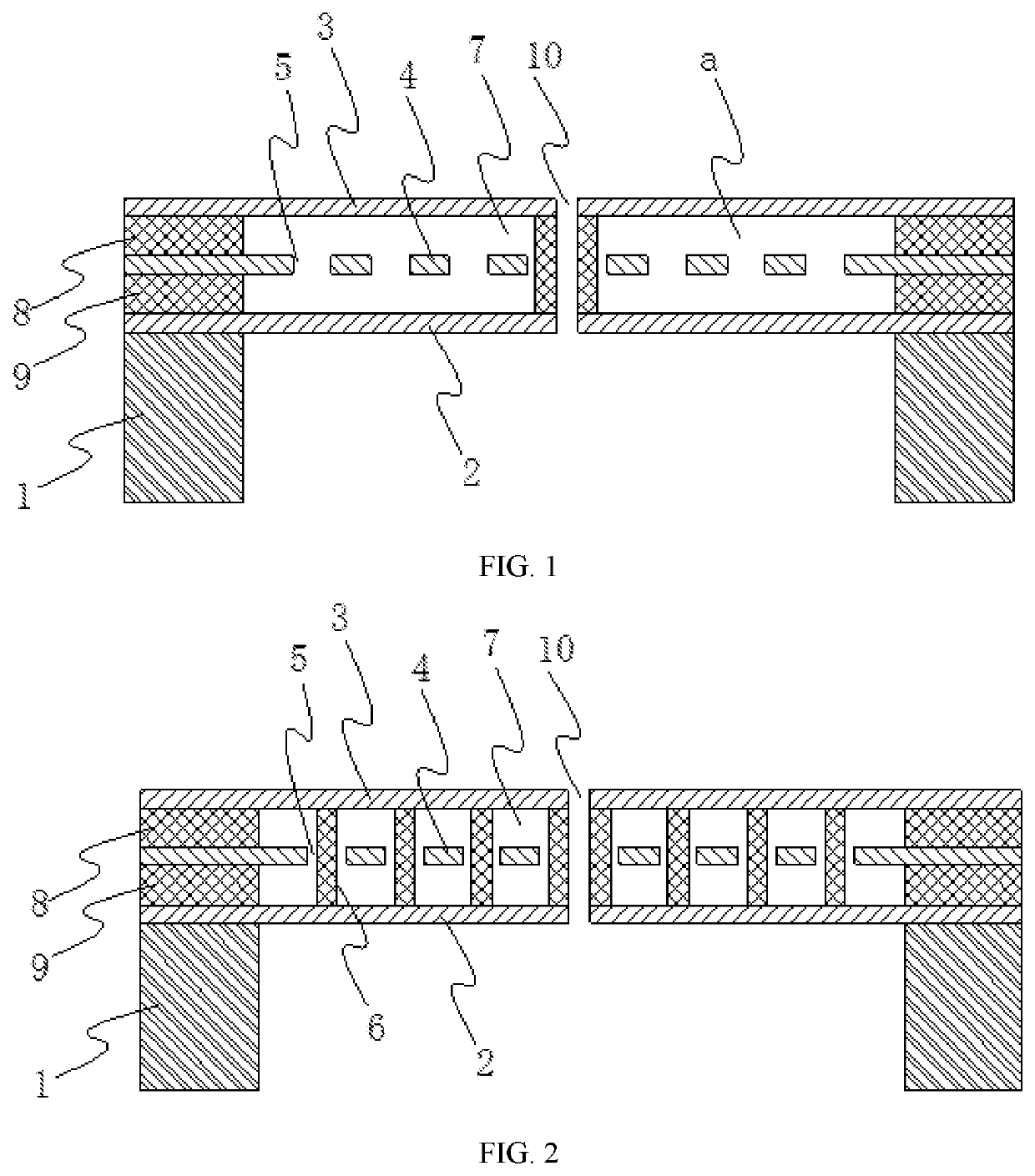
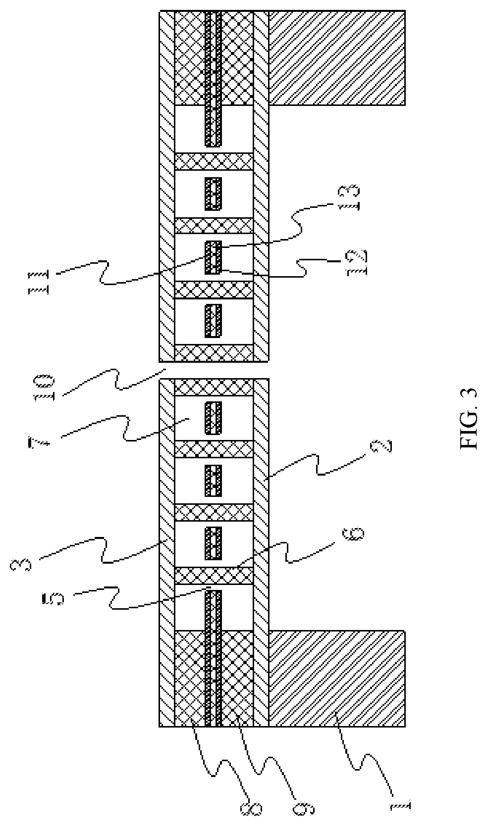
[0030]Various exemplary embodiments of the present invention will now be described in detail with reference to the accompanying drawings. It should be noted that the relative arrangement, numerical expressions and numerical values of the components and steps set forth in these embodiments do not limit the scope of the present invention unless otherwise specified.

[0031]The following description of at least one exemplary embodiment is in fact merely illustrative and is in no way intended as a limitation to the present invention and its application or use.

[0032]Techniques and devices known to those of ordinary skill in the relevant art may not be discussed in detail but where appropriate, the techniques and devices should be considered as part of the description.

[0033]Among all the examples shown and discussed herein, any specific value should be construed as merely illustrative and not as a limitation. Thus, other examples of exemplary embodiments may have different values.

[0034]It sh...


PUM


Abstract

A MEMS microphone, which comprises a substrate, a first vibrating diaphragm and a second vibrating diaphragm is provided. A sealed cavity is formed between the first vibrating diaphragm and the second vibrating diaphragm. A back electrode unit is located in the sealed cavity, forms a capacitor structure with the first vibrating diaphragm and with the second vibrating diaphragm respectively, and is provided with a plurality of through holes that penetrate through two sides thereof. The sealed cavity is filled with a gas whose viscosity coefficient is smaller than that of air. According to the MEMS microphone disclosed by the present invention, by filling the sealed cavity with a gas whose viscosity coefficient is smaller than that of air, the acoustic resistance when the two vibrating diaphragms move relative to the back electrode can be reduced greatly, thereby reducing the noise of the microphone. Meanwhile, by the use of a gas with a low viscosity coefficient for filling, the pressure in the sealed cavity is consistent with the pressure of an external environment, thereby avoiding the problem of vibrating diaphragm deflection caused by pressure difference and ensuring the performances of the microphone.

Description

CROSS-REFERENCE TO RELATED APPLICATIONS[0001]This application is a National Stage of International Application No. PCT / CN2017 / 113952, filed on Nov. 30, 2017, which claims priority to Chinese Patent Application No. 201711192077.3, filed on Nov. 24, 2017, both of which are hereby incorporated by reference in their entireties.BACKGROUNDTechnical Field[0002]The present invention relates to the field of acoustic-electronics, in particular to a microphone, and more particularly to an MEMS microphone.Description of Related Art[0003]The MEMS (Micro Electro Mechanical System) microphone is a microphone made based on the MEMS technology. A vibrating diaphragm and a back electrode are important components in the MEMS microphone and form a capacitor integrated on a silicon wafer, thereby realizing the acoustic-electric conversion.[0004]Such a traditional capacitive microphone is generally provided with through holes on its back electrode in order to balance the pressure between the vibrating di...

Claims


Application Information

Patent Timeline
Patent Type & Authority Applications(United States)
IPC IPC(8): H04R19/04H04R7/02H04R19/00H04R1/04
CPCH04R19/005H04R19/04H04R2201/003H04R7/02H04R1/04H04R1/28
Inventor ZOU, QUANBOWANG, ZHEDONG, YONGWEI
Owner WEIFANG GOERTEK MICROELECTRONICS CO LTD
Why Eureka
Try Eureka