Movable carrier auxiliary system and vehicle auxiliary system
Inactive Publication Date: 2020-07-09
ABILITY OPTO ELECTRONICS TECH
View PDF1 Cites 3 Cited by
Summary
Abstract
Description
Claims
Application Information
AI Technical Summary
This helps you quickly interpret patents by identifying the three key elements:
Problems solved by technology
Method used
Benefits of technology
Benefits of technology
The patent text describes a technical solution for improving the optical image capturing module of a vehicle electronic rear-view mirror by using structural size design and refractive power combination of at least two optical lenses to reduce the size and increase the amount of light entering the module. Additionally, the text describes a movable carrier auxiliary system that includes a first transparent assembly, a second transparent assembly, an electro-optic medium layer, at least one transparent electrode, at least one reflective layer, and at least one transparent conductive layer, which can produce stable reversible change in color and transparency by enabling the application of an external voltage or current.
Problems solved by technology
However, most of the rearview mirrors have limitations and disadvantages in use under certain driving conditions.
Usually, the rearview mirror reflects the front light from the overtaking or subsequent vehicles, which causes the driver to have a visual dizziness, so that the driver's visual ability will be rapidly reduced in an instant, increasing the driver's reaction time that front obstacles become visible.
Moreover, based on the structural design of the traditional car, all of the rearview mirrors have their own blind vision area in the corresponding installation position, so that the driver cannot completely obtain the actual road information outside of the car via the images shown by the rearview mirrors.
However, the viewable area provided by the left or right rear view mirror does not help the driver to know the blind vision information that the left or right rear view mirror does not display.
Therefore, in the above specific actions for driving a vehicle, the driver needs to constantly change the line of sight to obtain the road condition information, and cannot pay attention to the road conditions in all directions in time, which may cause a car accident or a collision event.
Method used
Image
Click on the blue label to locate the original text in one second.
Reading with bidirectional positioning of images and text.
Examples
first optical embodiment
[0168]As shown in FIG. 2A and FIG. 2B, wherein a lens group of an optical image capturing module 10 of a first optical embodiment of the present invention is illustrated in FIG. 2A, and FIG. 2B shows curve diagrams of longitudinal spherical aberration, astigmatic field, and optical distortion of the optical image capturing module in the order from left to right of the first optical embodiment. The optical image capturing module 10 of the first optical embodiment includes, along an optical axis from an object side to an image side, a first lens 110, an aperture 100, a second lens 120, a third lens 130, a fourth lens 140, a fifth lens 150, a sixth lens 160, an infrared rays filter 180, an image plane 190, and an image sensor 192.
[0169]The first lens 110 has negative refractive power and is made of plastic. An object-side surface 112 thereof, which faces the object side, is a concave aspheric surface, and an image-side surface 114 thereof, which faces the image side, is a concave asphe...
second optical embodiment
[0229]As shown in FIG. 3A and FIG. 3B, an optical image capturing module 20 of the second optical embodiment of the present invention includes, along an optical axis from an object side to an image side, a first lens 210, a second lens 220, a third lens 230, an aperture 200, a fourth lens 240, a fifth lens 250, a sixth lens 260, a seventh lens 270, an infrared rays filter 280, an image plane 290, and an image sensor 292.
[0230]The first lens 210 has negative refractive power and is made of glass. An object-side surface 212 thereof, which faces the object side, is a convex spherical surface, and an image-side surface 214 thereof, which faces the image side, is a concave spherical surface.
[0231]The second lens 220 has negative refractive power and is made of glass. An object-side surface 222 thereof, which faces the object side, is a concave spherical surface, and an image-side surface 224 thereof, which faces the image side, is a convex spherical surface.
[0232]The third lens 230 has p...
third optical embodiment
[0243]As shown in FIG. 4A and FIG. 4B, an optical image capturing module of the third optical embodiment of the present invention includes, along an optical axis from an object side to an image side, a first lens 310, a second lens 320, a third lens 330, an aperture 300, a fourth lens 340, a fifth lens 350, a sixth lens 360, a seventh lens 370, an infrared rays filter 380, an image plane 390, and an image sensor 392.
[0244]The first lens 310 has negative refractive power and is made of glass. An object-side surface 312 thereof, which faces the object side, is a convex spherical surface, and an image-side surface 314 thereof, which faces the image side, is a concave spherical surface.
[0245]The second lens 320 has negative refractive power and is made of glass. An object-side surface 322 thereof, which faces the object side, is a concave spherical surface, and an image-side surface 324 thereof, which faces the image side, is a convex spherical surface.
[0246]The third lens 330 has posit...
PUM
Abstract
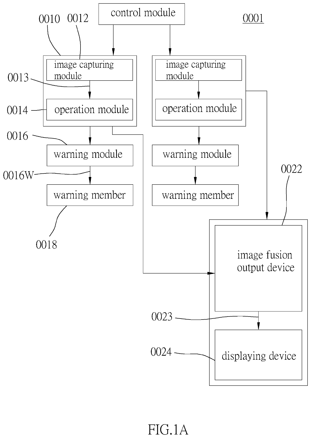
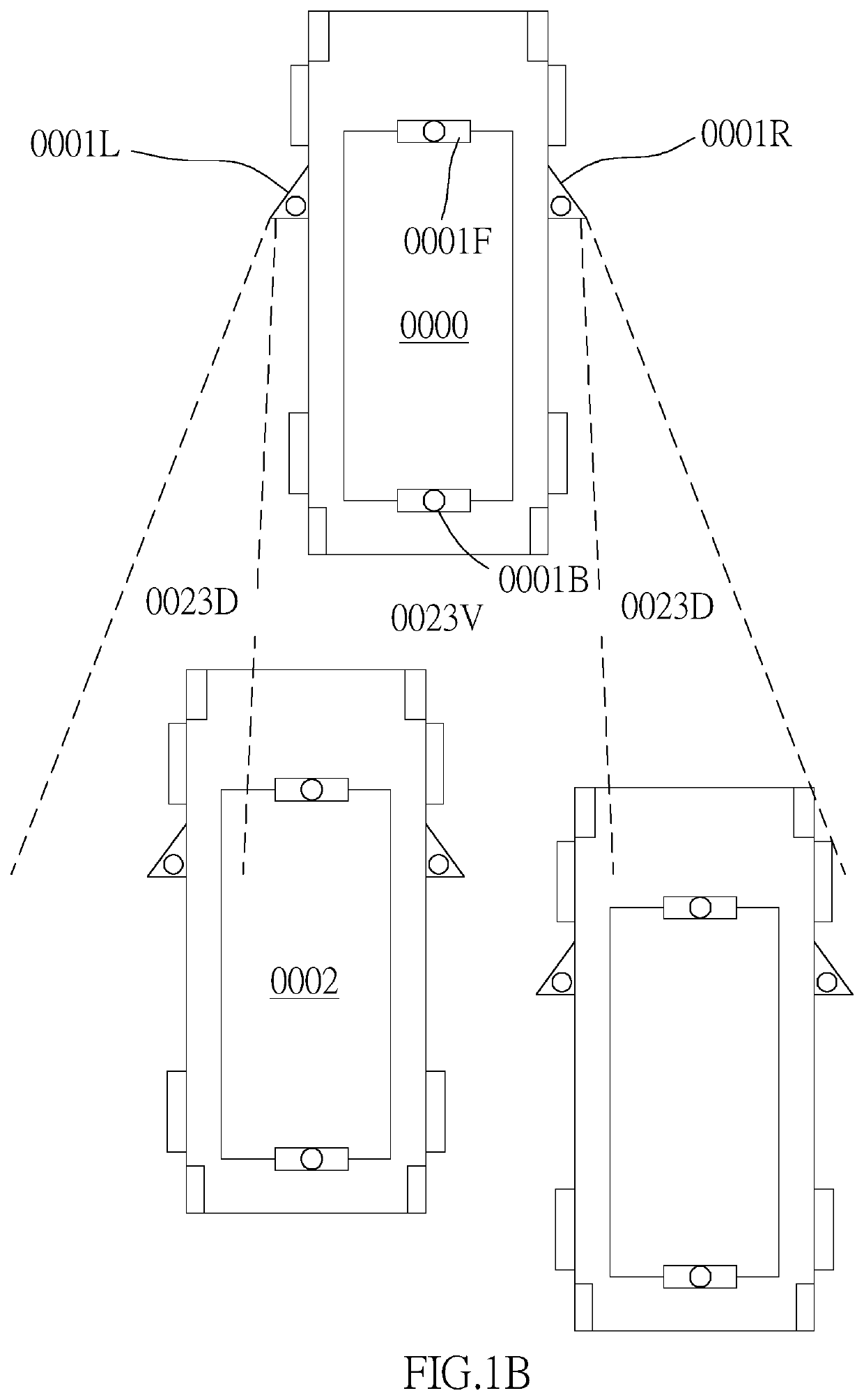
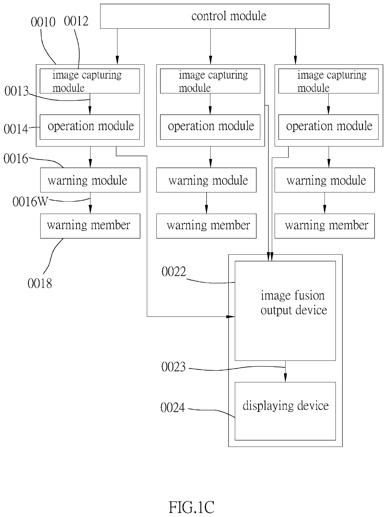
A movable carrier auxiliary system includes at least two optical image capturing systems respectively disposed on a left portion and a right portion of a movable carrier, at least one image fusionoutput device, and at least one displaying device. Each optical image capturing system includes an image capturing module and an operation module. The image capturing module captures and produces an environmental image surrounding the movable carrier. The operation module electrically connected to the image capturing module detects at least one moving object in the environmental image to generate a detecting signal and at least one tracking mark. The image fusionoutput device is disposed inside of the movable carrier and is electrically connected to the optical image capturing systems, thereby to receive the environmental image to generate a fusion image. The displaying device is electrically connected to the image fusionoutput device to display the fusion image and the at least one tracking mark.
Description
BACKGROUND OF THE INVENTIONTechnical Field[0001]The present invention generally relates to a movable carrier auxiliary system, and more particularly to an auxiliary system that could visualize an external environment with a wide viewing angle and could identify and track an object in the environment.Description of Related Art[0002]With frequent commercial activities and the rapid expansion of transportation logistics, people are more dependent on the mobile vehicle such as car or motorcycle. At the same time, drivers are paying more and more attention to the protection of their lives and property when driving, and therefore, in addition to the performance and the comfort of the mobile vehicle, it is also considered whether the mobile vehicle to be purchased provides sufficient safety guards or auxiliary devices. Under this trend, in order to increase the safety of vehicles, automobile manufacturers or vehicle equipment design manufacturers have developed various driving safety prote...
Claims
Application Information
Patent Timeline
Application Date:The date an application was filed.
Publication Date:The date a patent or application was officially published.
First Publication Date:The earliest publication date of a patent with the same application number.
Issue Date:Publication date of the patent grant document.
PCT Entry Date:The Entry date of PCT National Phase.
Estimated Expiry Date:The statutory expiry date of a patent right according to the Patent Law, and it is the longest term of protection that the patent right can achieve without the termination of the patent right due to other reasons(Term extension factor has been taken into account ).
Invalid Date:Actual expiry date is based on effective date or publication date of legal transaction data of invalid patent.

