Eureka AIR delivers breakthrough ideas for toughest innovation challenges, trusted by R&D personnel around the world.

Battery pack balancing systems and control logic for multi-pack electric-drive motor vehicles

a multi-pack, electric-drive technology, applied in the direction of batteries, hybrid vehicles, secondary cells, etc., can solve the problems of system control problems, undesirable battery system degradation and inefficiencies, and differences in capacities, states of charge, discharge rate, impedances, etc., to achieve balanced before, improve battery system efficiency, and safe connection and operation

Active Publication Date: 2020-07-16
GM GLOBAL TECH OPERATIONS LLC
View PDF0 Cites 5 Cited by
  • Summary
  • Abstract
  • Description
  • Claims
  • Application Information

AI Technical Summary

Benefits of technology

The patent describes a new system for balancing the voltage and capacity of multiple battery packs used in electric vehicles. This balancing protocol helps to ensure that each pack operates efficiently and has a consistent lifespan. This system achieves this by using a combination of software and hardware, which helps to improve overall battery system efficiency and prolong the life of the battery pack. This technology is particularly useful for heavy electric vehicles that require multiple battery packs to achieve a calibrated range.

Problems solved by technology

Utilizing numerous battery packs, however, inherently leads to differences in capacities, states of charge, discharge rates, impedances, and / or voltages between the distinct battery sections.
Multiple battery packs wired in electrical parallel may pose a system control problem due to this disparity in SOC between battery packs.
This behavior may result in undesirable battery system degradation and inefficiencies.
A representative control algorithm periodically “wakes” the vehicle during power off, and rebalances the traction battery packs prior to a predicted driving event.

Method used


Image

  • Battery pack balancing systems and control logic for multi-pack electric-drive motor vehicles
  • Battery pack balancing systems and control logic for multi-pack electric-drive motor vehicles
  • Battery pack balancing systems and control logic for multi-pack electric-drive motor vehicles

Examples


Embodiment Construction

[0020]This disclosure is susceptible of embodiment in many different forms. Representative embodiments of the disclosure are shown in the drawings and will herein be described in detail with the understanding that these embodiments are provided as an exemplification of the disclosed principles, not limitations of the broad aspects of the disclosure. To that extent, elements and limitations that are described, for example, in the Abstract, Introduction, Summary, and Detailed Description sections, but not explicitly set forth in the claims, should not be incorporated into the claims, singly or collectively, by implication, inference or otherwise.

[0021]For purposes of the present detailed description, unless specifically disclaimed: the singular includes the plural and vice versa; the words “and” and “or” shall be both conjunctive and disjunctive; the words “any” and “all” shall both mean “any and all”; and the words “including,”“containing,”“comprising,”“having,” and the like, shall e...


PUM

PropertyMeasurementUnit
weightaaaaaaaaaa
alternating currentaaaaaaaaaa
currentaaaaaaaaaa

Abstract

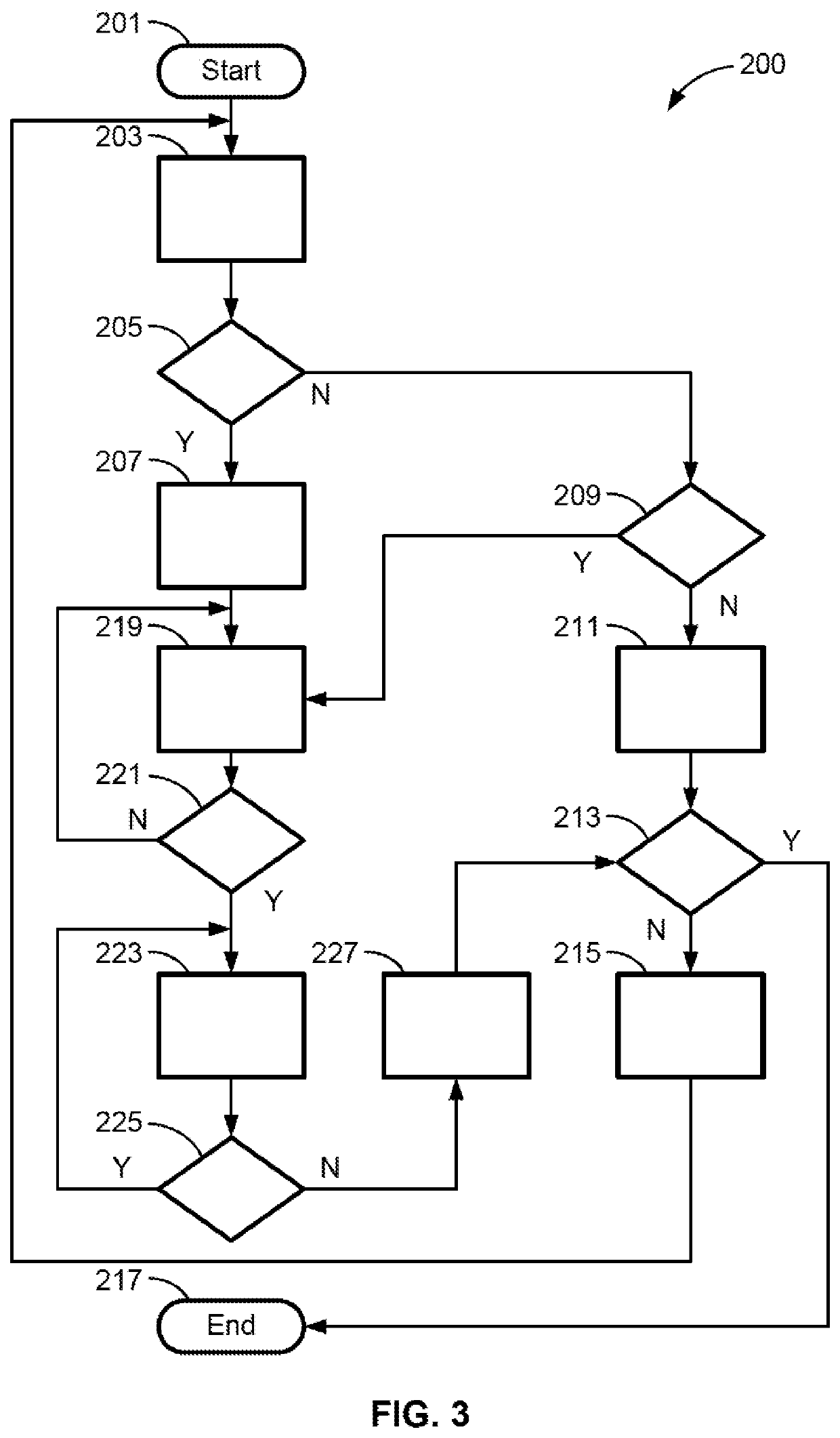
Presented are traction battery pack balancing systems, methods for making / operating such systems, and multi-pack, electric-drive motor vehicles with battery pack balancing capabilities. A method for controlling operation of a motor vehicle includes a vehicle controller: receiving a key-off command signal to power off the motor vehicle; determining if a difference between corresponding electrical characteristics of first and second traction battery packs is greater than a calibrated characteristic differential threshold; determining if a difference between corresponding battery pack capacities of the first and second traction battery packs is greater than a calibrated capacity differential threshold; and, responsive to the characteristic difference not being greater than the calibrated characteristic differential threshold and the capacity difference being greater than the calibrated capacity differential threshold, transmitting a key-on command signal to power on the motor vehicle, and a pack balancing command signal to reduce the capacity difference to below the calibrated capacity differential threshold.

Description

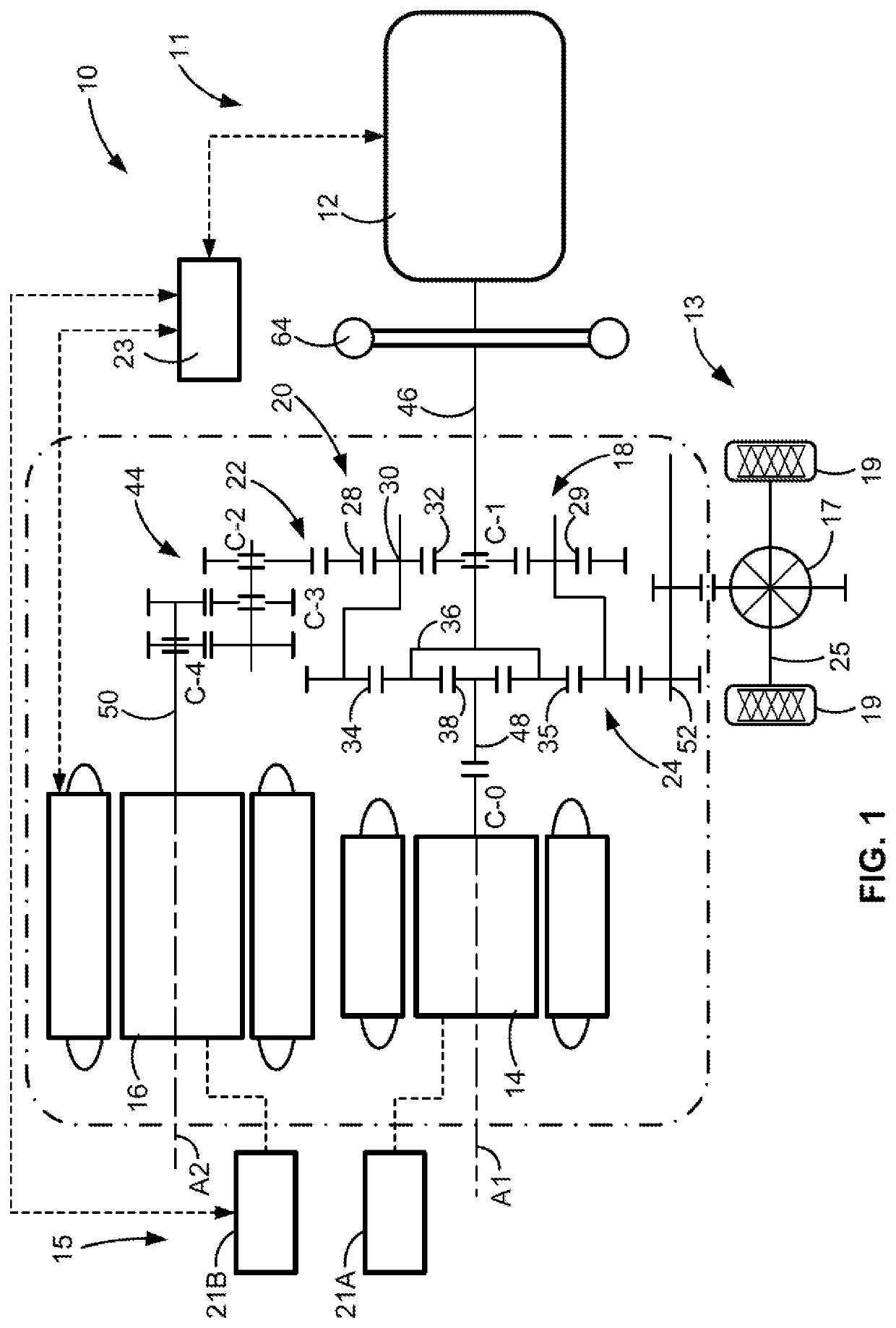
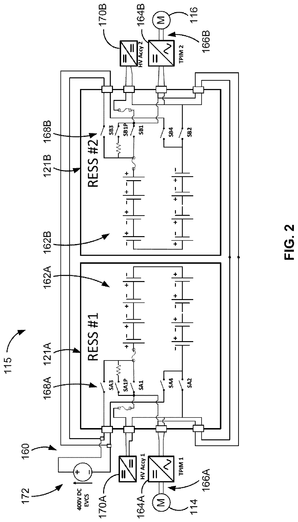
INTRODUCTION[0001]The present disclosure relates generally to hybrid and electric (“electric-drive”) motor vehicles. More specifically, aspects of this disclosure relate to battery pack balancing protocols for multi-pack, electric-drive vehicles.[0002]Current production motor vehicles, such as the modern-day automobile, are originally equipped with a powertrain that operates to propel the vehicle and power the vehicle's onboard electronics. In automotive applications, for example, the vehicle powertrain is generally typified by a prime mover that delivers driving power through a manually or automatically shifted multi-speed transmission to the vehicle's final drive system (e.g., differential, axle shafts, road wheels, etc.). Automobiles have historically been powered by a reciprocating-piston type internal combustion engine (ICE) assembly due to its ready availability and relatively inexpensive cost, light weight, and overall efficiency. Such engines include two and four-stroke comp...

Claims


Application Information

Patent Timeline
Patent Type & Authority Applications(United States)
IPC IPC(8): B60W20/11H02J7/14H02J7/00H01M10/44B60K6/28B60K6/485
CPCH02J7/0021B60W20/11B60K6/28B60K6/485H02J7/1423H01M10/441H02J7/0014B60L58/22B60L58/24B60L58/12B60L50/60H01M10/482Y02T10/70Y02E60/10B60K6/445B60K6/365B60W10/26B60W20/13B60W2540/06B60W2710/248H02J2310/48H02J7/0019H01M2220/20Y02T10/62
Inventor YE, SHAOCHUNGRENN, DANIEL P.LI, SHIFANGSTEELE, RUSSELL K.SEEMAN, GARRETT M.
Owner GM GLOBAL TECH OPERATIONS LLC
Why Eureka
Eureka Blog
Learn More