
Optical sensor based on shape memory between scattering and transparent modes

Inactive Publication Date: 2020-07-23
TECH UNIV EINDHOVEN
View PDF4 Cites 0 Cited by
  • Summary
  • Abstract
  • Description
  • Claims
  • Application Information

AI Technical Summary

Benefits of technology

The objective of this patent is to create a composite that solves the problems of previous methods, can be made quickly and inexpensively, and is attractive for commercial use.

Problems solved by technology

These electronical sensors typically cost more than 1 € / sensor and are far too expensive for broad application, such as on packaging of food, medicine and / or chemicals.
Also analogous organic time-temperature integrators (TTIs) are on the market, but these TTIs are generally multiple layer devices making them more expensive.
In the prior art there are some difficulties to scale up the manufacturing process.
Due to the fact that the surface of the stamp and the surface of the coating have to be as even as possible, contamination by particles, e.g. dust, complicates the manufacturing of the photonic TTI based on this mechanism.
Generating an even color shift using industrial embossing equipment is therefore very difficult, since gap accuracies are typically ±1 μm.
Furthermore, there are some difficulties associated with the use of planar CLC films for the production of time-temperature sensors.
First, the reflected wavelength in Bragg-reflection based optics is angle dependent, which results in the appearance of a different color when viewed at a different angle.

Method used


Image

  • Optical sensor based on shape memory between scattering and transparent modes
  • Optical sensor based on shape memory between scattering and transparent modes
  • Optical sensor based on shape memory between scattering and transparent modes

Examples


working examples

Example 1 (E1)

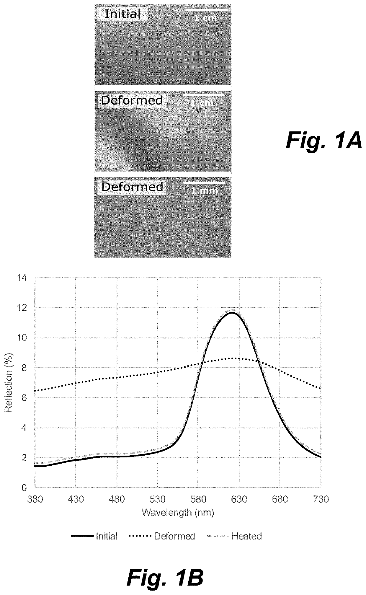
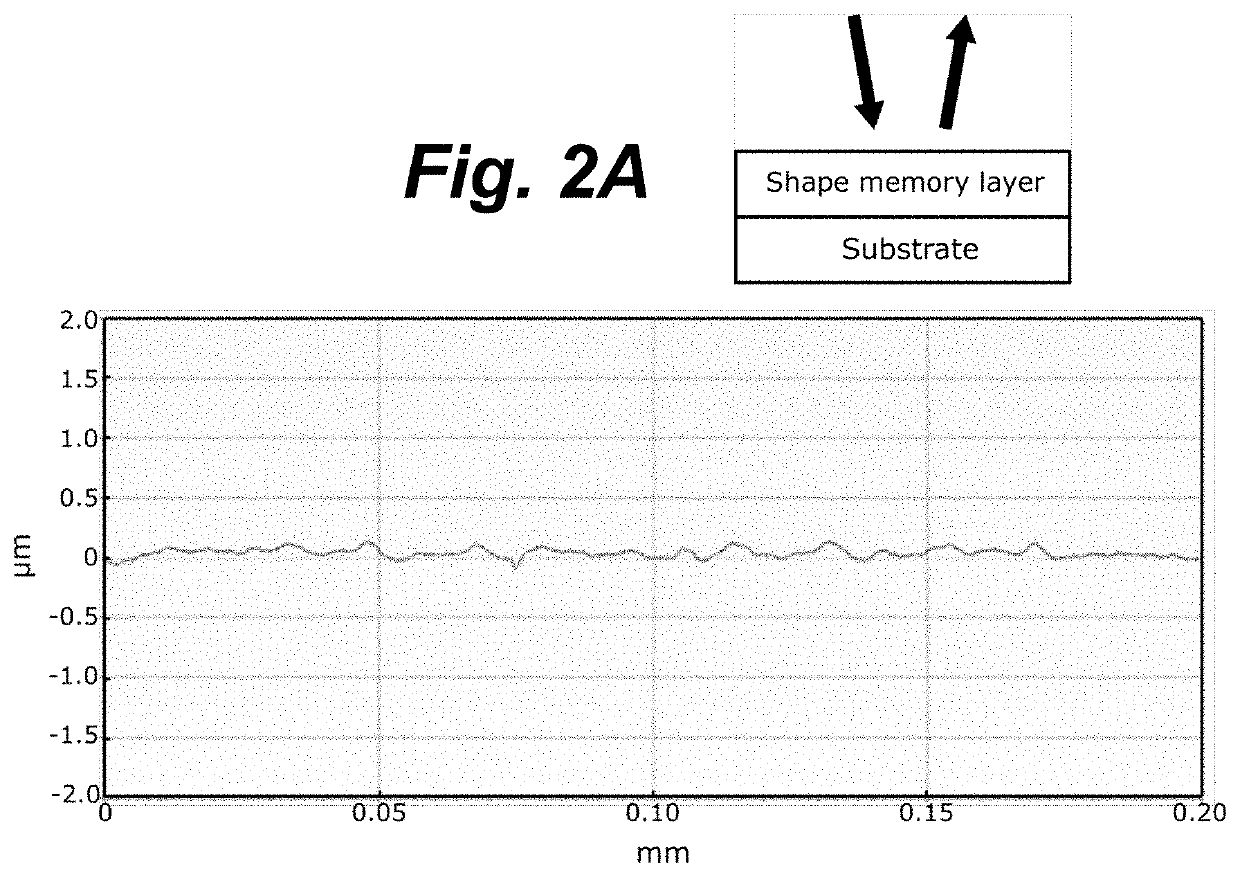
[0085]A composite comprising an upper layer made of CLC polymeric material (red color) and a black flexible polyethylene terephthalate (PET) substrate layer, wherein the upper layer has a thickness of approx. 2.5 μm measured according to profilometry, was manufactured by depositing a CLC ink on a black flexible polyethylene terephthalate (PET) substrate layer using flexographic printing (IGT Printability Tester F1 from IGT Testing System Pte Ltd.), and subsequently cured using UV-irradiation. The glass transition temperature (Tg) of the upper layer was determined by differential scanning calorimetry (DSC) to be approx. 15-30° C., with a mid-point at 18.4° C. The layer was subsequently deformed above its Tg (35° C., 30 s, 6 bar) using a hot-embossing stamp (KBA-Metronic GmbH). In the experimental setup, the surface of the upper layer was in direct contact with a roughly structured rubber (Ra≈1 μm), and the upper layer was quickly cooled to room temperature upon removal ...

example 3

[0091]A composite comprising a transparent shape-memory polymeric material as an upper layer and a clean glass slide as a sheet of a substrate layer and a red-reflecting CLC polymeric material as a further sheet of the substrate layer was manufactured by coating a clean glass slide with a commercially available monoacrylate (DSM), crosslinker, and photoinitiator, and subsequently cured with UV-radiation. The Tg,SMP of the upper layer was determined to be approximately 30° C. The glass slide containing the acrylic coating was subsequently placed on top of the red-reflecting CLC polymeric material used in E1 as an upper layer.

[0092]Prior to deformation, the reflection spectrum of the transparent acrylic coating with the background of the CLC polymeric material (FIG. 5B) is identical to the reflection spectrum of the initial non-deformed upper layer of the composite of E1 (FIG. 1B). The upper layer was subsequently deformed using identical conditions as in E1 and E2, resulting in a par...

example 4

[0093]A composite comprising an upper layer as in E3 and a glass substrate layer, wherein in the upper layer additionally CLC particles are comprised, was manufactured by coating a clean glass slide with the acrylic coating precursors from E3 and additionally, a small amount of a CLC particle mixture (according to WO 2015 / 120950 A1). The CLC particle mixture consisted of green- and blue-reflecting CLC polymer particles, with a Tg of approximately 60-70° C. After coating, the precursors were cured with UV-radiation to result in a particulate upper layer consisting of the CLC particle mixture embedded in the acrylic binder. To prevent scattering (prior to deformation), it was ensured that the refractive index of the CLC particles and acrylic binder were matching (n˜1.5). The substrate layer containing the upper layer was subsequently placed on top of a black PET background, to reveal a blue tint (FIG. 6A).

[0094]Prior to deformation, the reflection spectrum of the acrylic coating with ...


PUM

PropertyMeasurementUnit
Temperatureaaaaaaaaaa
Thicknessaaaaaaaaaa
Lengthaaaaaaaaaa

Abstract

A composite comprising an upper layer and a substrate layer, wherein the upper layer comprises a shape-memory polymeric material having a glass transition temperature Tg,SMP and being at least partially transparent for light in the VIS-range, characterized in that the upper layer comprises a surface, wherein the surface is at least partially a rough surface having an arithmetic average roughness Ra of at least 0.1 μm.

Description

FIELD OF THE INVENTION[0001]The invention pertains to a composite, a method of manufacturing such a composite and the use of such a composite.BACKGROUND OF THE INVENTION[0002]In logistics, e.g. transport and storage, numerous goods demand cooling to be protected against spoiling, aging and / or decomposition. The needed temperature in the cooling is substantially depending on the transported good. Frozen food needs a temperature of −18° C. or lower, fresh meat requires at most 4° C., milk and milk products have to be stored at 4 to 8° C. and chocolate demands a temperature of about 15 to 18° C.[0003]Also several medical goods such as vaccines, blood bags, infusions, bacterial cultures, chemical reagents, as well as pharmaceuticals demand cooling.[0004]Therefore, in logistics a cold chain was established to guarantee that the temperature sensitive goods are kept below the required temperature during the whole logistical process.[0005]To guarantee that the cold chain has not been broken...

Claims


Application Information

Patent Timeline
IPC IPC(8): G01K11/16B29C59/02
CPCB29K2105/0079B29C2059/023B29C59/022G01K11/165B29C59/026G01K3/005G01K5/483
Inventor NICKMANS, KOEN
Owner TECH UNIV EINDHOVEN
Learn More