Method and apparatus for flexible fronthaul physical layer split for cloud radio access networks
Active Publication Date: 2020-07-23
MAVENIR NETWORKS INC
View PDF0 Cites 19 Cited by
Summary
Abstract
Description
Claims
Application Information
AI Technical Summary
This helps you quickly interpret patents by identifying the three key elements:
Problems solved by technology
Method used
Benefits of technology
Benefits of technology
This patent describes an improved way to transmit data in a CRAN system, which increases efficiency and allows for flexibility in supporting various features needed for virtualization and commercialization. Specifically, it proposes an adaptive fronthaul interface that optimizes compression and decompression techniques based on factors like data rate, processing latency, fronthaul conditions, and application requirements. This can reduce fronthaul overhead, improve processing speed, and enable selective enabled and disabled compression techniques based on real-time needs. Overall, this patent provides a solution for optimizing data transmission in a CRAN system.
Problems solved by technology
However, there are various aspects which must be considered for the fronthaulinterface design since the splitting of the RAN functions into the RU and the BBU impacts the transport latency and bandwidth requirements.
As new wireless technologies and standards appear, MNOs are required to upgrade their eNB small cells, which upgrade usually involves high costs.
Method used
Image
Click on the blue label to locate the original text in one second.
Reading with bidirectional positioning of images and text.
Examples
case 1 (shown in fig.19)
Case 1 (shown in FIG. 19): Tx Diversity 1-CRS Port Ant0, 1 PRB
At DU:
[0202]For TxD case, d(q)(0), . . . , d(q)(Msymb(q)−1) M_q_sym modulation bits belonging to PDSCH ANT0 are packed into a PRB. All CRS REs for ANT0 are packed into a PRB for transmission and are unpacked at the RU.
At RU:
[0203]At RU, for single antenna port TxD, single layer is used, and mapping is defined as:
x(0)(i)=(0)(i)[0204]RU needs to map CRS into antenna ports.
case 2 (shown in fig.20)
Case 2 (Shown in FIG. 20): Tx Diversity 2-CRS Port Ant0, Ant1, and 1 PRB
At DU:
[0205]For TxD case, d(q)(0), . . . , d(q)(Msymb(q)−1) M_q_sym modulation bits belonging to PDSCH are packed to into a PRB. All CRS REs for ANT0, ANT1 are packed into a PRB for transmission and are unpacked at the RU.
At RU:
[0206]At RU, for two antenna port TxD, 2 layers are used, and mapping is defined as:
x(0)(i)=d(0)(2i)
x(1)(i)→d(0)(2i+1)[0207]For TxD, information for 2 layers are packed into a PRB for transmission and are unpacked at the RU. At RU, after layer mapping and precoding, CRS sequences for 2 antenna ports are mapped to the appropriate RE position, and the rest are left blank.
case 3 (shown in fig.21)
Case 3 (Shown in FIG. 21): Tx Diversity 4-CRS Port Ant0,1,2,3 and 1 PRB
At DU:
[0208]For TxD case, d(q)(0), . . . , d(q)(Msymb(q)−1) M_q_sym modulation bits belonging to PDSCH are packed to into a PRB. All CRS REs for ANT0, ANT1, ANT2, ANT3 are packed into a PRB for transmission and are unpacked at the RU.
At RU:
[0209]At RU, for two antenna port TxD, 4 layers are used, and mapping is defined as:
x(0)(i)=d(0)(4i)
x(1)(i)=d(0)(4i+1)
x(2)(i)=d(0)(4i+2)
x(3)(i)=d(0)(4i+3)
[0210]For TxD, REs for 4 layers are packed into a PRB for transmission and are unpacked at the RU. At RU, after layer mapping and precoding, CRS ports for 2 antenna ports are mapped to the appropriate RE position, and the rest are left blank.
PUM
Abstract
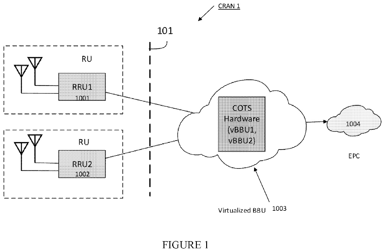
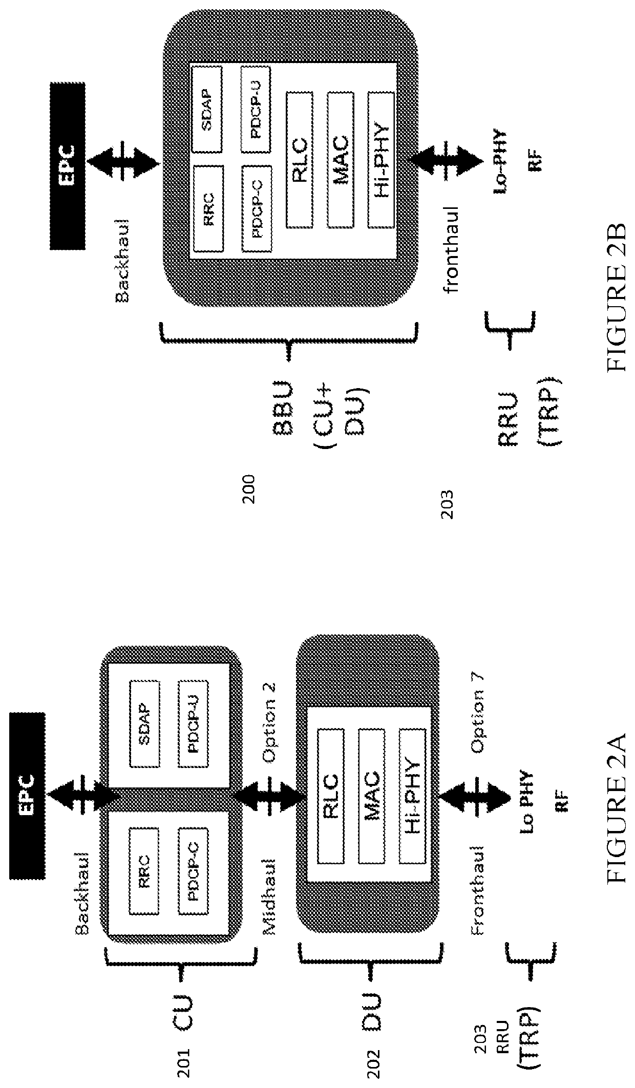
A cloud radio access network (CRAN) system includes a baseband unit (BBU) and a radio unit (RU) remote from the BBU. The fronthaul interface between the RU and the BBU includes a radio frequency interface (RF) functionality implemented in the RU, and implementation of asymmetrical physical layer (PHY) functionality split between the BBU and RU. The asymmetrical physical layer (PHY) functionality split includes: downlink (DL) antenna port mapping and DL precoding implemented in the RU; and the split of the PHY functionality for uplink (UL) at the antenna port mapping in the BBU. For the DL, precoding and resource element (RE) mapping to frequency resources is implemented in BBU, and RE mapping for antenna ports is implemented in the RU|[WA1]. The split also provides support for license-assisted access (LAA) in the CRAN system.
Description
BACKGROUND OF THE DISCLOSURE 1. Field of the Disclosure[0001]The present disclosure relates to systems and methods for radio access networks (RAN), and relates more particularly to RANs for 4th-Generation (4G) and 5th-Generation (5G) based mobile networks.2. Description of the Related Art[0002]Conventional RANs were built employing an integrated unit where the entire RAN was processed. Conventional RANs implement the protocol stack (e.g., Physical Layer (PHY), Media Access Control (MAC), Radio Link Control (RLC), Packet Data Convergence Control (PDCP) layers) at the base station (also referred to as the eNodeB or eNB). In addition, conventional RANs use application specific hardware for processing, which make the conventional RANs difficult to upgrade and evolve. As future networks evolve to have massive densification of networks to support increased capacity requirements, there is a growing need to reduce the capital and operating costs of RAN deployment and make the solution scala...
Claims
Application Information
Patent Timeline
Application Date:The date an application was filed.
Publication Date:The date a patent or application was officially published.
First Publication Date:The earliest publication date of a patent with the same application number.
Issue Date:Publication date of the patent grant document.
PCT Entry Date:The Entry date of PCT National Phase.
Estimated Expiry Date:The statutory expiry date of a patent right according to the Patent Law, and it is the longest term of protection that the patent right can achieve without the termination of the patent right due to other reasons(Term extension factor has been taken into account ).
Invalid Date:Actual expiry date is based on effective date or publication date of legal transaction data of invalid patent.

