Concentration control apparatus, zero point adjustment method, and program recording medium recorded with concentration control apparatus program

Active Publication Date: 2020-07-30
HORIBA STEC CO LTD
View PDF0 Cites 3 Cited by
  • Summary
  • Abstract
  • Description
  • Claims
  • Application Information

AI Technical Summary

Benefits of technology

[0025]As described, the concentration control apparatus according to the present invention makes it possible to automatically determine by itself the time point when the gas present in the measurement part where the concentration measurement mechanism performs the concentration measurement has been replaced with the other gas and the time point when the predetermined vacuum degree is achieved, and to appropriately make the zero adjustment with accuracy. Accordingly, without se

Problems solved by technology

However, if, for the zero adjustment of the concentration measurement mechanism, a semiconductor manufacturing process is regularly in

Method used


Image

  • Concentration control apparatus, zero point adjustment method, and program recording medium recorded with concentration control apparatus program
  • Concentration control apparatus, zero point adjustment method, and program recording medium recorded with concentration control apparatus program
  • Concentration control apparatus, zero point adjustment method, and program recording medium recorded with concentration control apparatus program

Examples


Example

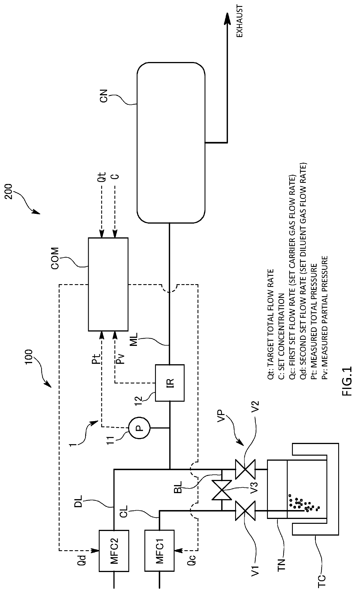
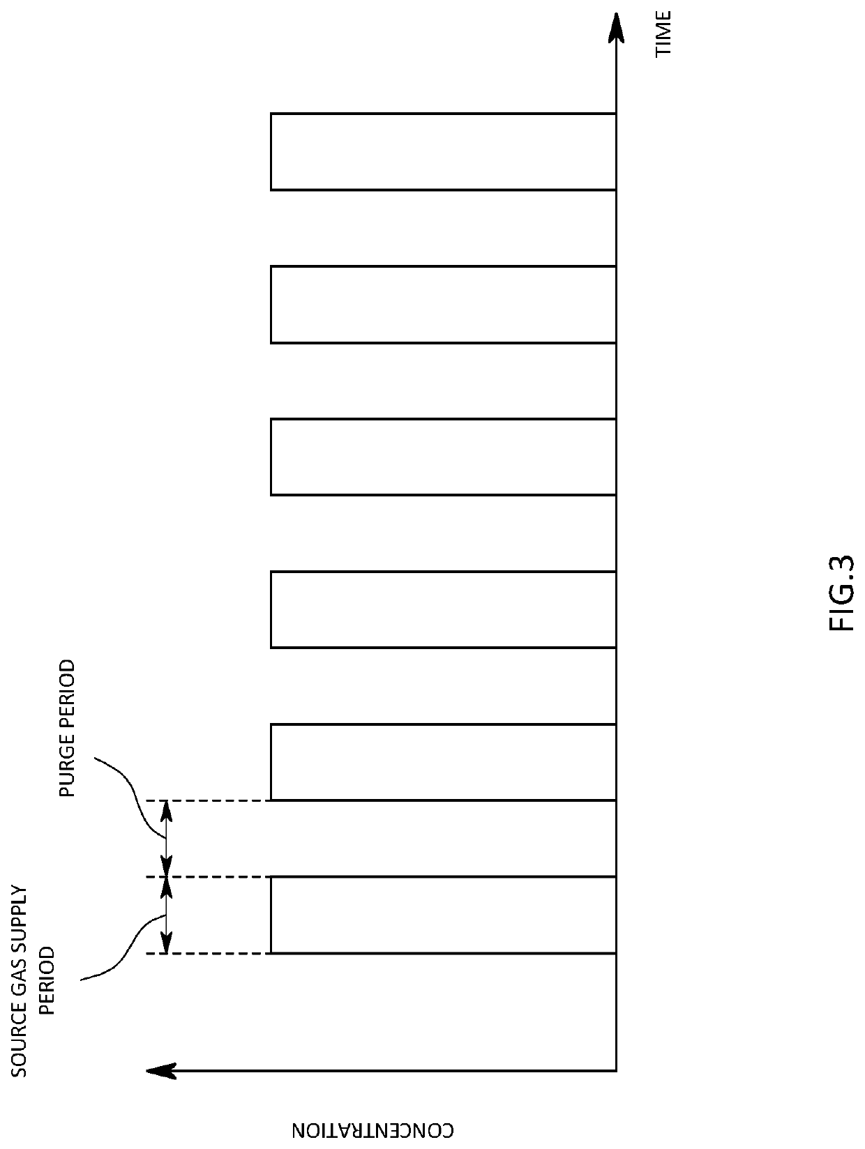
[0037]The concentration control system 200 in the first embodiment is one that supplies a predetermined set concentration of gas into a chamber CN such as a deposition chamber in a semiconductor manufacturing process. In the first embodiment, for example, atoms are deposited layer by layer on the surfaces of multiple wafers contained in the chamber CN by an atomic layer deposition (ALD) process. For this reason, the concentration control system 200 is configured to alternately repeat supply of gas containing a precursor and supply of purge gas not containing a precursor into the chamber CN.

[0038]As illustrated in FIG. 1, the concentration control system 200 includes, for example, a vaporizer VP that supplies carrier gas to a liquid material to vaporize it, and produces mixed gas of the carrier gas and source gas resulting from the vaporization of the material, and the concentration control apparatus 100 that controls the concentration of the source gas in the mixed gas produced by t...

Example

[0077]The concentration control system 200 in the second embodiment is one that performs concentration control that does not dilute mixed gas led out of a tank TN with diluent gas to bring concentration close to set concentration but, without using the diluent gas, control the total pressure of the mixed gas flowing through a lead-out flow path ML to bring the concentration of source gas contained in the mixed gas close to the set concentration.

[0078]That is, as compared with the first embodiment, the concentration control apparatus 100 of the second embodiment is different in that a control valve CV for controlling the total pressure of the mixed gas is provided in the lead-out flow path ML and in that the outputs of a concentration controller 2 are a first set flow rate for controlling the flow rate of carrier gas by a first mass flow controller MFC1 and the operation amount of the control valve CV.

[0079]More specifically, the concentration controller 2 in the second embodiment ou...

Example

[0085]In the concentration control system 200 in the third embodiment, only a control valve CV is provided in an introduction flow path CL, and concentration feedback control of the flow rate of carrier gas is performed using the control valve CV to thereby perform control so that the concentration of source gas in mixed gas flowing through a lead-out flow path ML is kept at set concentration.

[0086]That is, as compared with the first embodiment, the concentration control apparatus 100 of the third embodiment is different in that the control valve CV is provided in the introduction flow path CL and in that a concentration controller 2 controls the control valve CV in the introduction flow path CL on the basis of the deviation between the set concentration and measured concentration measured by a concentration measurement mechanism 1.

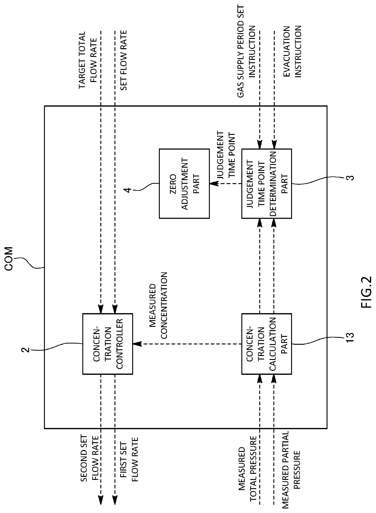
[0087]Even in the third embodiment configured as described, the configurations and operations of a judgement time point determination part 3 and a zero a...


PUM

PropertyMeasurementUnit
Pressureaaaaaaaaaa
Concentrationaaaaaaaaaa
Volumeaaaaaaaaaa

Abstract

A concentration control apparatus capable of appropriately making a zero adjustment of a concentration measurement mechanism without interrupting a semiconductor manufacturing process includes: a control valve that controls gas flowing through a lead-out flow path; a concentration measurement mechanism that measures the concentration of source gas contained in gas flowing through the lead-out flow path; a concentration controller that controls the control valve so that the deviation between measured concentration measured by the concentration measurement mechanism and preset set concentration decreases; a judgement time point determination part that determines a judgement time point that is the time point when the gas present in a measurement part where the concentration measurement mechanism performs the concentration measurement has been replaced with other gas; and a zero adjustment part that makes a zero adjustment of the concentration measurement mechanism at or after the judgement time point.

Description

TECHNICAL FIELD[0001]The present invention relates to a concentration control apparatus.BACKGROUND ART[0002]For example, in a semiconductor manufacturing process, carrier gas is introduced into a tank containing liquid material or solid material, then the material is vaporized to produce source gas, and the source gas is led out of the tank as mixed gas of the carrier gas and the source gas. The concentration of the source gas contained in such mixed gas is kept at a predetermined set concentration by a concentration control apparatus and supplied to a chamber (see Patent Literature 1).[0003]As a conventional concentration control apparatus of a pressure control type, there is one including: a concentration measurement mechanism that is provided in a lead-out flow path for leading mixed gas out of a tank; a control valve that controls the total pressure of the mixed gas in the lead-out flow path; and a concentration controller that controls the control valve on the basis of measured...

Claims


Application Information

Patent Timeline
IPC IPC(8): C23C16/455C23C16/448
CPCC23C16/45544C23C16/4481H01L21/67017G05D11/138H01L21/67253C23C16/4482C23C16/45525G05D7/0635
Inventor SHIMIZU, TORUMINAMI, MASAKAZU
Owner HORIBA STEC CO LTD
Why Eureka
Try Eureka