
Direct backlight module and liquid crystal display device

a liquid crystal display and backlight module technology, applied in non-linear optics, instruments, optics, etc., can solve problems such as difficult to realize thin designs, and achieve the effects of reducing the thickness of direct backlight modules, and increasing the light-emitting angl

Active Publication Date: 2020-08-27
WUHAN CHINA STAR OPTOELECTRONICS TECH CO LTD
View PDF0 Cites 9 Cited by
  • Summary
  • Abstract
  • Description
  • Claims
  • Application Information

AI Technical Summary

Benefits of technology

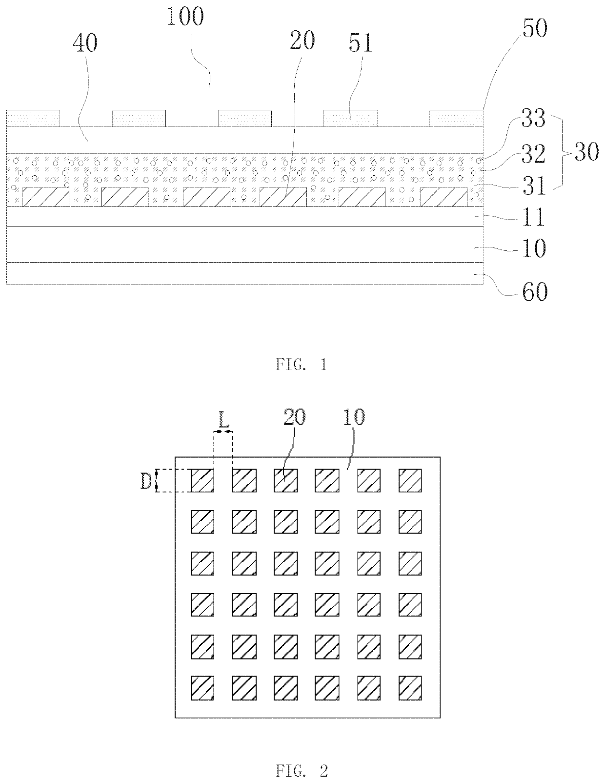
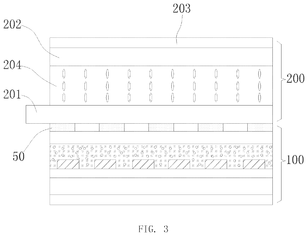
The present invention provides a direct backlight module that allows for even light mixing in a thinner design for a thin and narrow-frame liquid crystal display device. By using haze particles and a metal grating layer, the light-emitting angle is increased and the reflected light is repeatedly reflected between the phosphor particles and the haze particles to perform a light mixing, reducing the thickness of the direct backlight module. The metal grating layer also acts as a reflective polarizer and a lower polarizer in the liquid crystal display device, reducing the total thickness and the problem of attenuation of reflection affect caused by multiple films separately disposed between the lower polarizer and the backlight module.

Problems solved by technology

Accordingly, the direct backlight module can satisfy a narrow-frame design, but hard to realize a thin design.

Method used


Image

  • Direct backlight module and liquid crystal display device
  • Direct backlight module and liquid crystal display device

Examples


Embodiment Construction

[0026]The following content combines with the drawings and the embodiment for describing the present invention in detail. It is obvious that the following embodiments are only some embodiments of the present invention. For the person of ordinary skill in the art without creative effort, the other embodiments obtained thereby are still covered by the present invention. The present invention is not limited to the above embodiments.

[0027]Here, it should be noted that in order to avoid obscuring the present disclosure because of unnecessary detail, the figures only show structure and / or processing steps that are closely related according to the present solution, and the other details that are not related to the present disclosure is omitted.

[0028]The embodiment of the present invention provides with a direct backlight module. With reference to FIG. 1, the direct backlight module 100 include a substrate 10, a blue LED chip 20, an optical conversion layer 30, a transparent dielectric laye...


PUM

PropertyMeasurementUnit
widthaaaaaaaaaa
widthaaaaaaaaaa
diameteraaaaaaaaaa

Abstract

A direct backlight module is disclosed, and includes: a substrate having a driving circuit layer; multiple blue LED chips disposed on the substrate, and the multiple blue LED chips are electrically connected to the driving circuit layer; an optical conversion layer covered on the multiple blue LED chips, wherein the optical conversion layer includes a colloidal material, multiple phosphor particles and multiple haze particles disposed in the colloidal material, the optical conversion layer converts a blue light emitted from the multiple blue LED chips into a white light; and a transparent dielectric layer and a metal grating layer sequentially formed on the optical conversion layer. A liquid crystal display device is also disclosed. The direct backlight module can reduce the thickness of the liquid crystal device, which is beneficial to realize a thin and narrow-frame liquid crystal display device.

Description

FIELD OF THE INVENTION[0001]The present invention relates to a liquid crystal display technology field, and more particularly to a direct backlight module, and a liquid crystal display device including the direct backlight module.BACKGROUND OF THE INVENTION[0002]A Liquid Crystal Display (LCD) is a flat and ultra-thin display device, which is formed by a certain number of color or black and white pixels, and being placed in front if a light source or a reflection surface. The liquid crystal display device has a low power consumption, and has features of high display quality, small size and light weight so that the LCD is favored by everyone and became a mainstream of the display device. Most of the liquid crystal display device in the market is a backlight type liquid crystal display device including a liquid crystal panel and a backlight module. The liquid crystal panel and a backlight module are disposed oppositely. The backlight module provides a display light source to the liquid...

Claims


Application Information

Patent Timeline
Patent Type & Authority Applications(United States)
IPC IPC(8): G02F1/13357G02F1/1335
CPCG02F1/133603G02F2001/133614G02F1/133528G02F1/133605G02F1/133611G02F1/133514G02F2001/133612G02F1/133606G02F1/133536G02F1/13362G02F2201/30G02F1/133607G02F1/133614G02F1/133612
Inventor ZHA, GUOWEICUI, HONGQING
Owner WUHAN CHINA STAR OPTOELECTRONICS TECH CO LTD
Learn More