
A high pressure barrel

Active Publication Date: 2020-09-10
NEO MECHANICS LTD
View PDF0 Cites 0 Cited by
  • Summary
  • Abstract
  • Description
  • Claims
  • Application Information

AI Technical Summary

Benefits of technology

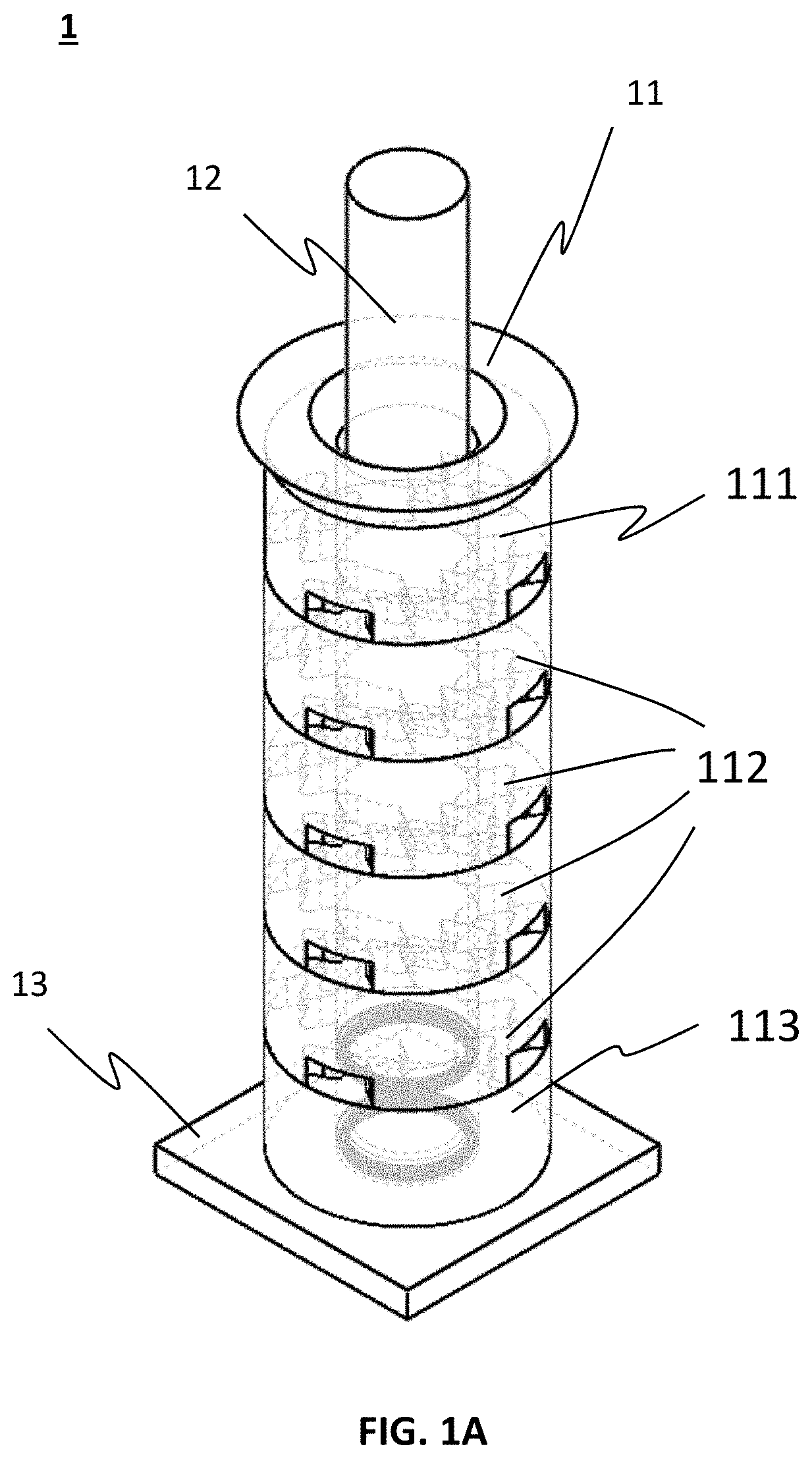
The present invention provides a high-pressure piston-cylinder assembly with enhanced pressure capacity, improved durability, reduced power loss, and significantly reduced leakage. It also includes one or more coiled felt seals that can contract and dilate to reduce friction and leakage during the up-down strokes of the piston in the cylinder.

Problems solved by technology

When use in some applications, such as waste compaction or food processing, the cylinder may be subject to an extreme high pressure.
To enhance the pressure capacity, simply increasing the cylinder wall thickness would be ineffective and impractical as at higher values of internal pressure, small increase in pressure requires large increase in wall thickness.
However, nickel-based superalloys are very expensive and are difficult to machine, limiting the maximum practical size and greatly increasing the cost.
On the other hand, the piston rings installed around the piston are traditionally rubber O-rings which may result in leakage problem at high internal pressure because the rubber will be squeezed out of gap between the cylinder wall and the piston when exposed to an internal pressure at above 450 Pa.

Method used


Image

  • A high pressure barrel
  • A high pressure barrel
  • A high pressure barrel

Examples


Embodiment Construction

[0041]Hereinafter, embodiments of the present invention will be described with reference to the figures. It should be noted that the embodiments described herein are not intended to limit the invention in accordance with the claims, and it is to be understood that each of the elements and combinations thereof described with respect to the embodiments are not strictly necessary to implement the aspects of the present invention. Additionally, well-known elements of the disclosure will not be described in detail or will be omitted so as not to obscure the relevant details of the disclosure.

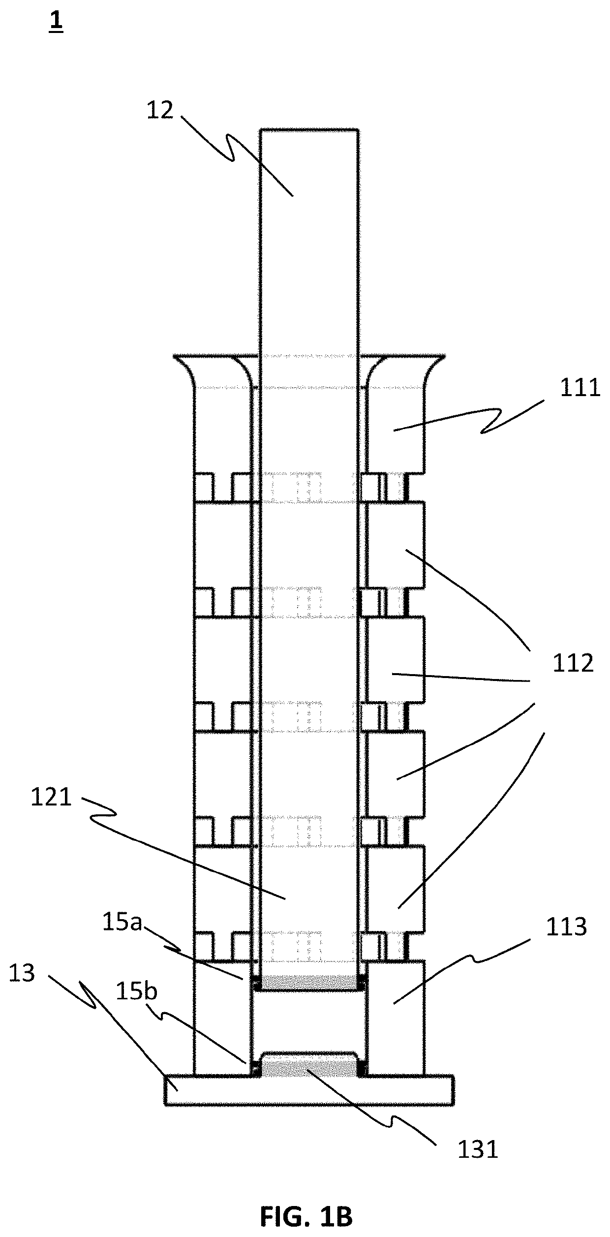
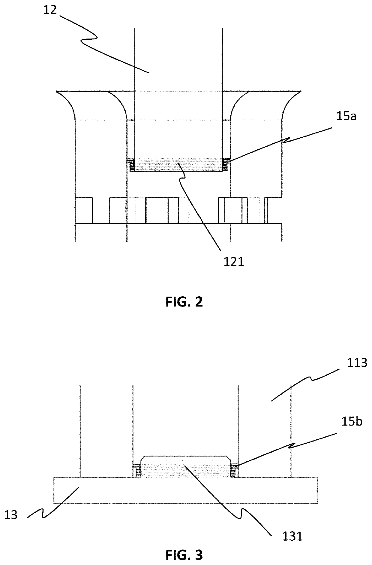
[0042]FIGS. 1A and 1B depict an isometric view and a sectional view, respectively, of a high-pressure piston-cylinder assembly 1 for compaction treatment in accordance with one embodiment of the present invention. As show in FIGS. 1A and 1B, the piston-cylinder assembly 1 comprises a cylinder 11 comprising a plurality of sections including a top section 111, one or more middle sections 112 and a bott...


PUM


Abstract

The present invention provides a high-pressure piston-cylinder assembly for compaction treatment comprising a cylinder comprising a plurality of sections which are longitudinally stacked and joined to form the cylinder; a piston configured for moving in and along the cylinder; and a base configured for being coupled with the cylinder to provide mechanical support to the cylinder; wherein each of the sections includes one or more releasing channels for releasing of liquid or gas fluid generated during compaction treatment. The high-pressure piston-cylinder assembly is sealed by one seal having a helical coiled sealing ring structure tightly encircling the piston, and another seal encircling a cylindrical sealing block protruded from the base and into the cylinder. The resulting piston-cylinder assembly can be more effectively manufactured, has better durability and tolerance in high-pressure operation.

Description

CROSS-REFERENCES TO RELATED APPLICATIONS[0001]This application is related to the PCT International Application No. PCT / CN2012 / 071634 filed Feb. 24, 2012; the disclosure of which is incorporated herein by reference in its entirety.COPYRIGHT NOTICE[0002]A portion of the disclosure of this patent document contains material, which is subject to copyright protection. The copyright owner has no objection to the facsimile reproduction by anyone of the patent document or the patent disclosure, as it appears in the Patent Office patent file or records, but otherwise reserves all copyright rights whatsoever.FIELD OF THE INVENTION[0003]The present disclosure relates generally to piston-cylinder technology and more specifically relates to a piston-cylinder mechanical assembly for high-pressure processing.BACKGROUND OF THE INVENTION[0004]Piston-cylinder technology has been applied in internal combustion engines, hydraulic seals, reciprocating pumps, gas compressors, pneumatic cylinders, and othe...

Claims


Application Information

Patent Timeline
IPC IPC(8): B30B15/02B30B15/28
CPCB30B15/28B30B15/02F04B53/143F04B53/162F04B53/02F16J15/164F16J15/22B30B1/32
Inventor KO, STANLEY MOON KAICHANG, KYONG TAE
Owner NEO MECHANICS LTD
Learn More