Bit condition monitoring system and method

a technology for monitoring systems and bits, applied in the field of drill bits, can solve problems such as teeth breakage, increase the total cost of operation, and increase the risk of drilling failures

Active Publication Date: 2020-09-10
MCGILL UNIV
View PDF0 Cites 4 Cited by
  • Summary
  • Abstract
  • Description
  • Claims
  • Application Information

AI Technical Summary

Problems solved by technology

In addition to having high initial capital costs, factors such as maintenance, manpower, and energy requirements act to increase the total cost of operating this machinery.
Teeth breakage may occur as a result of repeated impacts and fatigue in the harsh drilling environment.
Teeth breakage is one of the major problems in drilling with a drill bit known as tricone.
Bearing failure results from the effects of wear on the bearing elements as well as the cones and cutting structure will result in progressive wear in the cones rotary structure and bearing failure eventually.
Any observation of a rapid rise in torque while under constant operating conditions is a sign of bearing failure.
A bearing failure requires immediate bit replacement.
Unfortunately, the requirement of constant operating conditions and rock type is not the case in the open pit mining environment.
This dynamic, and often unknown, in-situ geology makes it difficult to determine if penetration rate is decreasing or torque is spiking because of bit wear / failure or because a new rock layer is being encountered.
This problem results in an essential limitation on performance-based drill bit wear monitoring and is a motivation to explore new approaches and models for bit wear monitoring.

Method used


Image

  • Bit condition monitoring system and method
  • Bit condition monitoring system and method
  • Bit condition monitoring system and method

Examples


Embodiment Construction

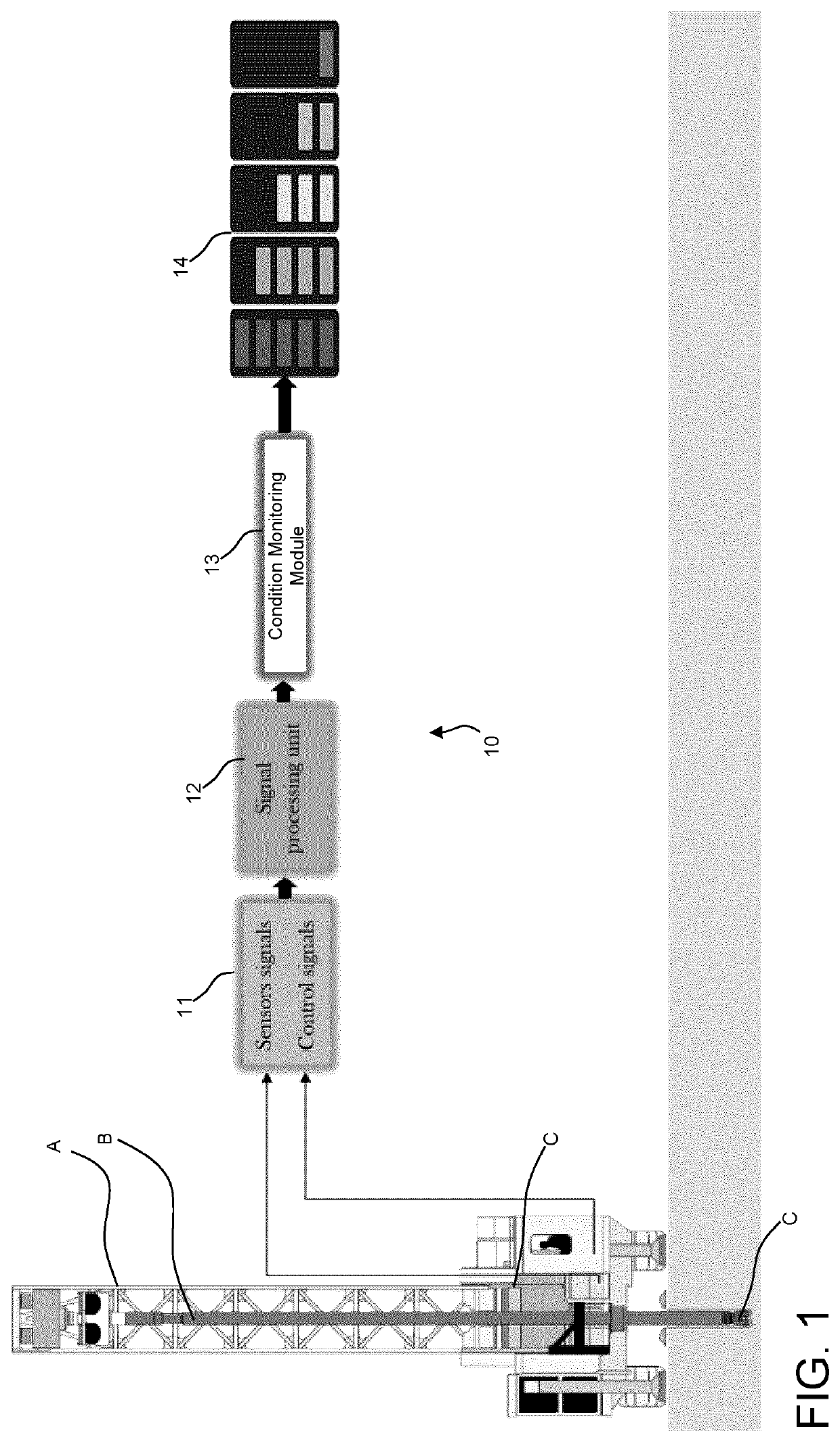
[0037]According to the present disclosure, there is provided a method and system for bit wear condition monitoring. Referring to FIG. 1, there is illustrated a drilling rig having a drill mast A supporting a drill pipe B. Drill bit(s) C is at the leading end of the drill pipe B, as is conventionally known. In accordance with an embodiment, the drill bit C is a tricone bit, although other types of drill bits may be used in accordance with the present disclosure. In another embodiment, there is a single tricone bit C per drill pipe B. In another embodiment, the drilling rig is an automated drill rig, as the drilling is performed by an automated control system. A bit condition monitoring system 10 described herein may be integrated in the drilling rig, for instance as part of the control system of the drilling rig. As such, the bit condition monitoring system 10 may assist in the operation of any automated drilling operation.

[0038]The bit condition monitoring system in accordance with ...


PUM


Abstract

A system for monitoring a bit condition in a drilling operation comprises a processor unit and a non-transitory computer-readable memory communicatively coupled to the processing unit and comprising computer-readable program instructions executable by the processing unit for: obtaining signals representative of at least vibrations of a drilling mast having at least one bit during a drilling operation; interpreting the signals into vibration values; continuously monitoring the vibration values in real time; and assessing and outputting a condition of the bit as a function of the continuous monitoring of the vibration values.

Description

CROSS-REFERENCE TO RELATED APPLICATION[0001]The present application claims the priority of U.S. Provisional Patent Application No. 62 / 566,786, filed on Oct. 2, 2017, and incorporated herein by reference.TECHNICAL FIELD[0002]The present application relates to drilling bits used in mining operations, and more particularly to a method and system for monitoring a bit condition.BACKGROUND OF THE ART[0003]For the majority of open-pit mining operations, the first stage of comminution involves the drilling and blasting of an intact rock mass. In order to maximize the efficiency and placement of explosive energy, vertical or inclined blast holes are created using large hydraulically or electrically-controlled drill rigs. The applied weight and rotational forces produced by these machines are then transferred to a drill bit which advances through the rock mass by a process of induced compressive and shearing failure mechanisms. In addition to having high initial capital costs, factors such as...

Claims


Application Information

Patent Timeline
Patent Type & Authority Applications(United States)
IPC IPC(8): E21B12/02E21B44/00
CPCE21B12/02E21B44/00
Inventor HASSANI, FARAMARZ (FERRI) P.RAFEZI, HAMED
Owner MCGILL UNIV
Why Eureka
Try Eureka