Method for preventing a risk of freezing in a reducing-agent feeding device of a selective catalytic reduction system

a catalytic reduction and reducing agent technology, applied in the direction of engines, mechanical equipment, machines/engines, etc., can solve the problems of reducing the protection against potential consuming electrical energy, and limiting the diagnosis of freezing by the controller processor, so as to avoid the freezing of the reducing agent and prolong the interval between waking up. , the effect of preventing the risk of freezing

Active Publication Date: 2020-09-10
VITESCO TECH GERMANY GMBH
View PDF0 Cites 2 Cited by
  • Summary
  • Abstract
  • Description
  • Claims
  • Application Information

AI Technical Summary

Benefits of technology

[0015]The technical effect of the present invention is that the device for supplying the reduction system is not systematically purged when the engine is stopped, which purge could prove not to be necessary and costs energy, when purging and when refilling the system at the next starting of the vehicle. This is obtained by monitoring the temperature of the reducing agent at determined intervals in order to check whether this temperature is above the freezing temperature of the reducing agent, and that there is therefore no risk of the reducing agent freezing and damaging the system, and notably its injector, through an increase in volume.
[0026]Advantageously, the intervals can be calibrated as a function of the outside temperature, the intervals being shorter, the lower the outside temperature. This makes it possible to avoid the reducing agent freezing between two awakenings and switch-offs of the controller, this being something that could happen when the outside temperature drops sharply.

Problems solved by technology

Because of this purge and because of the resultant refilling for each driving cycle, a large quantity of urea needs to be pumped and reinjected, and this creates wearing of the pump and consumes electrical energy.
However, the technology according to the prior art of a switch that draws no current does present the following disadvantages.
The first disadvantage is a limit on the diagnosis of freezing by the processor of the controller.
Specifically, as long as the bimetallic strip has not closed below a low temperature, it is not possible for the processor to diagnose possible freezing.
The second disadvantage is that it is impossible to modify the threshold at which the awakening of the controller is triggered by calibrating or reprogramming the bimetallic strip.
A third disadvantage is that the constant presence of the bimetallic strip in combination with the supply of power to the controller may present a risk of unwanted triggering of the controller, which then places unnecessary demands on the battery.
A fourth disadvantage is that the device requires at least one additional relay in order to definitively cut off the electrical power supply to the controller after the system has been purged at a temperature close to the temperature at which the reducing agent freezes.

Method used


Image

  • Method for preventing a risk of freezing in a reducing-agent feeding device of a selective catalytic reduction system

Examples


Embodiment Construction

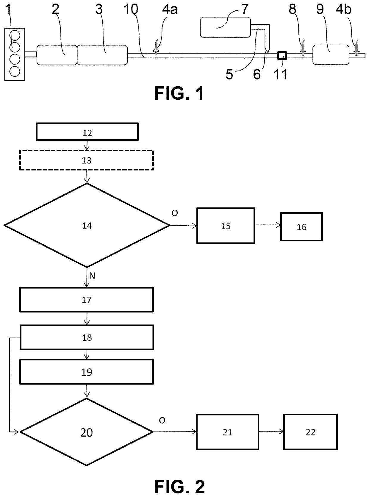
[0033]In what follows, upstream and downstream are to be considered in the sense of a flow of exhaust gases along an exhaust line.

[0034]Reference is made to FIG. 1 which shows a combustion engine 1 and an exhaust line 10 for removing the exhaust gases originating from combustion in the combustion engine 1. The exhaust line 10 may comprise, in the vicinity of an exhaust manifold of the engine 1, an oxidation catalytic converter 2 and a particulate filter 3, for a compression-ignition engine 1, notably a diesel engine 1 or engine running on gas oil.

[0035]In the case of a controlled-ignition combustion engine, notably an engine running on gasoline or on a mixture containing gasoline, the line 10 may comprise a three-way catalytic converter and a gasoline particulate filter.

[0036]An upstream nitrogen oxides probe 4a, also referred to as an upstream NOx probe is positioned downstream of the particulate filter 3. All the features relating to the reduction catalytic converter 2, to the par...


PUM


Abstract

Disclosed is a method for preventing a risk of freezing in a device for supplying reducing agent to a selective catalytic reduction system in an exhaust line, a freezing temperature specific to the agent being stored in memory, the system including a controller operating the system and emitting pulses to an injector, the controller being inactive when the engine is switched off. With the combustion engine switched off, the controller is woken up at predetermined intervals to initiate an emission of a specific electric pulse to the injector with measurements of a current-strength and voltage of the electric pulse providing a value of the electrical resistance of the injector. A temperature of the reducing agent at the injector is estimated as a function of the measured resistance and, when at least the temperature thus estimated is below the freezing temperature, a purge of the device is initiated.

Description

BACKGROUND OF THE INVENTIONField of the Invention[0001]The present invention relates to a method for preventing a risk of freezing in a device for supplying reducing agent to a selective catalytic reduction system in an exhaust line of a motor vehicle combustion engine, the removal of nitrogen oxides being carried out using selective catalytic reduction by injecting a quantity of reducing agent into the line.Description of the Related Art[0002]More than 95% of diesel engines will be equipped with a device for treating nitrogen oxides in the exhaust line. This could apply in the very near future to gasoline fueled engines.[0003]In order to do this, in motor vehicles, in particular with a diesel engine, it is known practice to equip an internal combustion engine exhaust line with a selective catalytic reduction system having injection of reducing agent into the line, the monitoring-control unit receiving the estimates or measurements of quantities of nitrogen oxides exiting through th...

Claims


Application Information

Patent Timeline
Patent Type & Authority Applications(United States)
IPC IPC(8): F01N3/20
CPCF01N2900/12F01N3/208F01N2900/08F01N2610/10F01N2900/1821F01N2610/1453F01N2900/1811F01N3/2066F01N9/00F01N11/00F01N2560/06F01N2560/12F01N2610/02F01N2610/146F01N2610/148F01N2610/1486F01N2610/1493Y02A50/20Y02T10/12Y02T10/40
Inventor BARBIER, PASCALSIROP, SYLVAIN
Owner VITESCO TECH GERMANY GMBH
Why Eureka
Try Eureka