Eureka AIR delivers breakthrough ideas for toughest innovation challenges, trusted by R&D personnel around the world.

Waveform analyzer

Active Publication Date: 2020-09-17
SHIMADZU CORP
View PDF2 Cites 2 Cited by
  • Summary
  • Abstract
  • Description
  • Claims
  • Application Information

AI Technical Summary

Benefits of technology

The waveform analyzer described in this patent allows for efficient and accurate peak detection and correction. The system displays information about likely peaks, making them easy to differentiate from less reliable peaks. This reduces the burden on the user and improves the overall throughput of waveform analysis. Additionally, in cases where a large number of peaks are observed, the invention prevents incorrect or incomplete checking by reducing the number of peaks to be checked by the user.

Problems solved by technology

An actual chromatogram waveform has such problems as the superposition of various types of noise, fluctuation of the baseline, or overlap of the peaks originating from a plurality of kinds of components.
Therefore, it is difficult to correctly detect a peak from a chromatogram waveform.
Furthermore, since it is from the start difficult to apply a single specific algorithm to chromatogram waveforms which vary in baseline shape or peak shape, the operator also needs to select an algorithm to be used from a plurality of peak detection algorithms prepared beforehand.
Such tasks are considerably burdensome for the operator and significantly hinder an improvement of the efficiency of the analytical task.
Furthermore, since the analytical task requires a certain amount of skill and experience, only a limited group of individuals can take charge of the task.
These factors make it difficult to ensure the accuracy, reproducibility or reliability of the analysis result.
However, those algorithms still rely on the operator performing a considerable number of tasks.
In some cases, the detection result obtained by the automatic peak detection using such an algorithm may be inappropriate.
In such a case, the task of visually checking and manually correcting the starting and ending points of all peaks requires an enormous amount of time.

Method used


Image

  • Waveform analyzer
  • Waveform analyzer
  • Waveform analyzer

Examples


Embodiment Construction

8]One embodiment of the waveform analyzer according to the present invention is hereinafter described in detail.

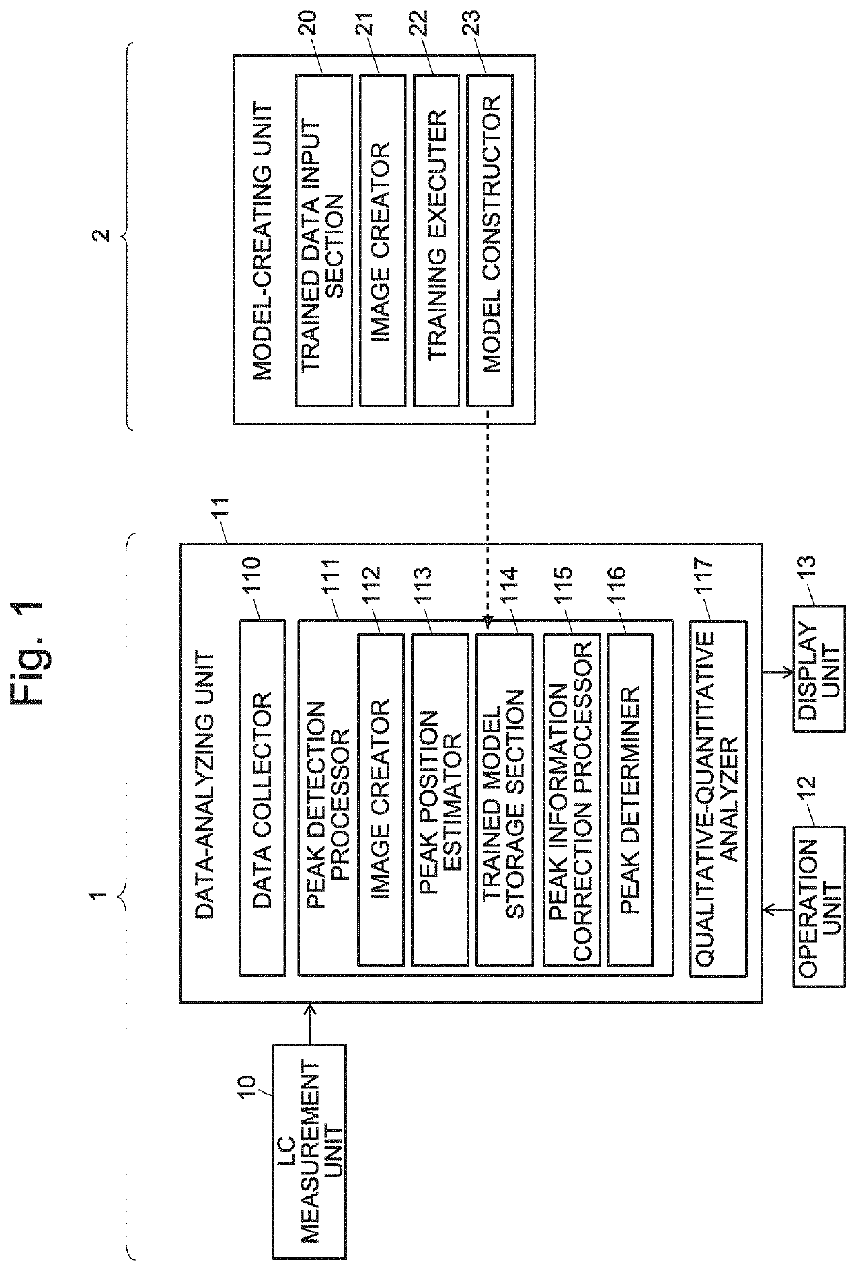
[0049]FIG. 1 is a schematic configuration diagram of a liquid chromatograph (LC) system using one embodiment of the waveform analyzer according to the present invention and a system for creating a trained model to be used in the LC system.

[0050]The LC system 1 includes an LC measurement unit 10, data-analyzing unit 11, operation unit 12 and display unit 13. Though not shown, the LC measurement unit 10 includes a liquid supply pump, injector, column, column oven, detector and other components. The LC measurement unit 10 performs an LC analysis on a given sample and acquires chromatogram data which show the temporal change of the intensity of the signal produced by the detector.

[0051]The data-analyzing unit 11 includes a data collector 110, peak detection processor 111, qualitative-quantitative analyzer 117 and other functional blocks. The peak detection processor 111 furthe...


PUM


Abstract

When chromatogram data for a target sample have been acquired, a peak position estimator determines an estimated result of the position of the starting and / or ending point of a peak as well as the confidence value representing the reliability of the estimation, using a trained model stored in the trained model storage section. Normally, a plurality of estimated results of the starting point and / or ending point of the peak are acquired for one peak. A peak information correction processor identifies a candidate having the highest confidence as a prime candidate, and superposes a plurality of candidates including the prime candidate, with their respective confidence values, on a displayed chromatogram. An operator referring to the confidence values selects a peak which needs close checking or correction, and corrects the starting point and / or ending point of the selected peak, for example, by selecting and indicating a candidate other than the prime candidate.

Description

TECHNICAL FIELD[0001]The present invention relates to a waveform analyzer configured to analyze the waveform of a signal acquired with an analyzing device. For example, the present invention is suitable for an analysis of the waveform of a signal acquired with various analyzing devices, such as a chromatogram waveform acquired with a gas chromatograph (GC), liquid chromatograph (LC) or similar apparatus, a mass-spectrum waveform acquired with a mass spectrometer, an absorption-spectrum waveform acquired with a spectrophotometer or similar apparatus, as well as an X-ray-spectrum waveform acquired with an X-ray analyzer.BACKGROUND ART[0002]In a gas chromatograph or liquid chromatograph apparatus, a sample containing various components is introduced into a column. While the sample is passing through the column, the various components are separated from each other in the temporal direction. The separated components are detected with a detector located at the exit end of the column. Base...

Claims


Application Information

Patent Timeline
IPC IPC(8): G01N30/86
CPCG01N30/8634G01N30/8693G01N30/8631G01N30/88
Inventor OSOEKAWA, TAKESHIHIDA, YUSUKEKANAZAWA, YUZIKANAZAWA, SHINJIYAMADA, YOHEIYASUDA, HIROYUKIKUNISAWA, AKIHIRO
Owner SHIMADZU CORP
Why Eureka
Eureka Blog
Learn More