
Eureka
For R&D, Eureka makes reading and utilizing patents & technical documents easy.
Eureka AIR
Designed for self-driven R&D workflows. Generate viable solutions, solve complex R&D challenges, empower your innovation with AI.

Eureka Materials
Designed for material experts only. Revolutionize your material R&D, from search, analyze, to developing new materials.

TechResearch
Generate reliable direction feasibility study reports for your R&D in just a few steps.

TechSeek
Discover and master advanced knowledge NOW. Basics, ideas, possibilities, all at once.

TechMind
As an expert in R&D Theories, TechMind can generates customized viable solutions instantly.

TechRisk
Analyze your overall solution with one click, know your potential R&D risks in advance.

TechMonitor
Get weekly tech updates, stay abreast of the latest tech innovations and key insights.
Method to form multile electrical components and a single electrical component made by the method
- Summary
- Abstract
- Description
- Claims
- Application Information
AI Technical Summary
Benefits of technology
Problems solved by technology
Method used
Image

Examples
first embodiment
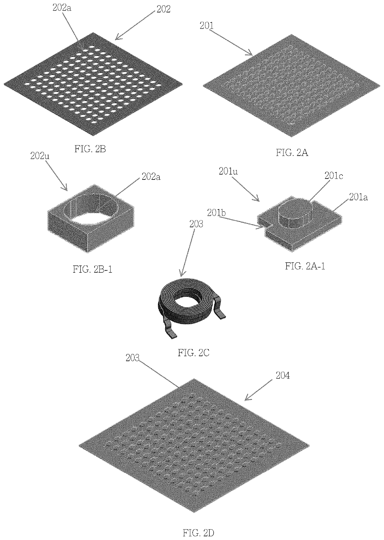
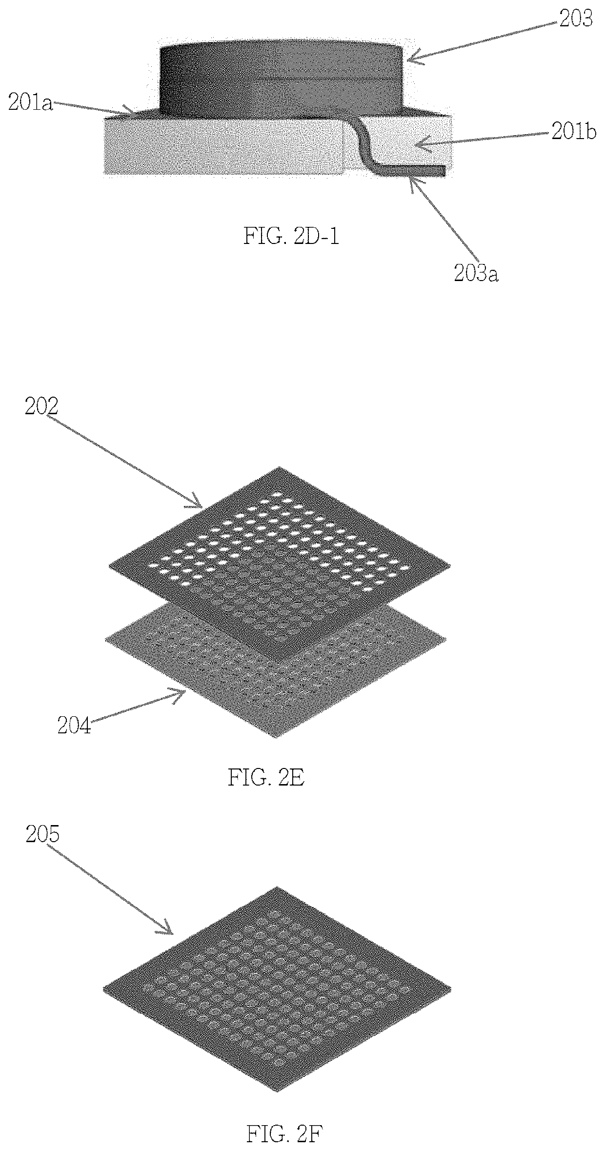
[0054]Please refer to FIG. 2A-2J, a plurality of through openings 201b are formed in the first magnetic sheet 201 as shown in FIG. 2A, wherein the first magnetic sheet 201 comprises a plurality of protrusions 201c on a top surface 201a of the first magnetic sheet 201, such as bumps or pillars, wherein each unit 201u of the first magnetic sheet 201 is illustrated in FIG. 2A-1; then, a plurality of coils 203 are disposed on the first magnetic sheet 201 to form a structure 204 as shown in FIG. 2D, wherein each coil 203 is formed by a corresponding conductive wire as shown in FIG. 2c, wherein a terminal part 203a of each conductive wire is disposed in a corresponding through opening 201b of the first magnetic sheet 201, as shown in FIG. 2D-1; then, a second magnetic sheet 202 is disposed on the first magnetic sheet 201 to form a structure 205, wherein the second magnetic sheet 202 comprises a plurality of through-holes 202a, as shown in FIG. 2B, wherein each unit of the second magnetic ...
second embodiment
[0060]This embodiment is similar to the first embodiment described above, wherein instead of printing the magnetic and adhesive material 206a on the second magnetic sheet 202 to encapsulate the coils 203 as described in the first embodiment, another magnetic layer or sheet can be disposed on the on the second magnetic sheet 202 to encapsulate the coils 203. That is, in FIG. 2G, instead of using the magnetic and adhesive material 206a to encapsulate the coils 203 so as to a form a structure 206, the magnetic and adhesive material 206a will be changed to a magnetic layer that is disposed on the second magnetic sheet 202 to encapsulate the coils 203 so as to a form a structure 206. Other descriptions can be inferred from the first embodiment and therefore it will not be described further for this second embodiment.
third embodiment
[0061]The first magnetic sheet 201, as shown in FIG. 2A, is provided here as shown in FIG. 3A (please refer to the first embodiment for the description of the first magnetic sheet 201); a plurality of coils 203 are disposed on the first magnetic sheet as shown in FIG. 3B; then, a magnetic and adhesive material is printed 300a on the first magnetic sheet 201 to encapsulate the coils 203 to from a structure 300, as shown in FIG. 3C; then, the structure 300 can be can be pressed and / or heated so as to form a magnetic body 350, as shown in FIG. 3D; then the magnetic body 350 can be cut into a plurality of pieces along a plurality of cutting line 308a, as shown in FIG. 3E, with each piece comprising a corresponding coil 203 encapsulated by a corresponding portion 207a of the magnetic body 207, as shown in FIG. 2J, wherein a side surface of the terminal part 203a, 203b of the conductive wire forming the coil 203 is exposed from said corresponding portion of the magnetic body 207a for form...
PUM
 Abstract
Description
Claims
Application Information
 - R&D Engineer
- R&D Manager
- IP Professional
- Industry Leading Data Capabilities
- Powerful AI technology
- Patent DNA Extraction
Browse by: Latest US Patents, China's latest patents, Technical Efficacy Thesaurus, Application Domain, Technology Topic, Popular Technical Reports.
© 2024 PatSnap. All rights reserved.Legal|Privacy policy|Modern Slavery Act Transparency Statement|Sitemap|About US| Contact US: help@patsnap.com