Switching power converter system

a power converter and converter technology, applied in the direction of power electronics conversion, efficient power electronics conversion, electric variable regulation, etc., can solve the problems of reducing reliability and disturbed behaviour, unable to provide for example a half-bridge switching power setting, and prior art concepts will have limitations, so as to improve characteristic switching properties and reduce electromagnetic interference (emi). , the effect of fast well-balanced transition times

Inactive Publication Date: 2020-09-24
HIENSCH INNOVATIONS
View PDF0 Cites 1 Cited by
  • Summary
  • Abstract
  • Description
  • Claims
  • Application Information

AI Technical Summary

Benefits of technology

[0014]According to the further aspect of the present invention a cluster comprising the parallel coupling of two or more of the at least two auxiliary units may further comprise low pass filter means subdivided in high side low pass filter means and low side low pass filter means, in which two auxiliary units included in the parallel coupling of the cluster may comprise a coupling between the high side terminals interposed by the high side low pass filter means, a coupling of the common side terminals and a coupling between the low side terminals interposed by the low side low pass filter means to set an attenuated frequency range between the high side terminals being interposed as well as to set an attenuated frequency range between the low side terminals being interposed. Subsequently a crosswise switching charge pump setting implemented with at least two auxiliary units and at least one interlace unit is configured to form a H8H topology of an interlace unit intermediately coupled in cascade with an auxiliary unit being pre-coupled and an auxiliary unit being post-coupled, in which the auxiliary unit being pre-coupled in cascade with the interlace unit is included in a parallel coupling of two or more of the at least two auxiliary units to form a cluster being pre-coupled to the interlace unit, and in which the auxiliary unit being p

Problems solved by technology

In general the semiconductor industry has made great progress in the last decennia's, however despite the great progress, it is still not possible to provide for example a half bridge switching power setting comprising only two series connected and counter phase driven semiconductors (MOSFET, IGBT, BJT) being operable to generate a switching output voltage of several kilovolts in combination with a high operational switching frequency as well as fast transition times.
In addition, it is to be noted that with the series connection of several semiconductors as described above the output capacitance resided in each constituted semiconductor will be series connected as well achieving by means of the series connection a decreased overall output capacitance obtaining reduced switching losses as well as reduced transition times. However tolerance of the constituted components may introduce divergent switching behaviour for each semiconductor taken alone resulting in reduced reliability as well as disturbed behaviour.
However due to a complex configuration of components and therefore hard to implement with respect to high frequency (HF) properties as well as an inevitable large amount of stray inductance due to a series connection of several semiconductors in combination with the additional deficiencies as described above, the prior art concept will have limitations in order to achieve a well-designed switching power converter setting.
However it is to be noted that the switching charge pump setting as shown in FIG. 1 as well as the opposite variant thereof exhibits a non-balanced circuit configuration resulting in case the respective switching elements are implemented with for example semicon

Method used


Image

  • Switching power converter system
  • Switching power converter system
  • Switching power converter system

Examples


Embodiment Construction

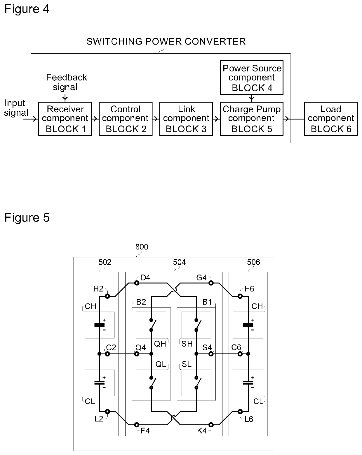
[0041]In accordance with the present invention a basic conceptual block diagram of a switching power converter system as shown in FIG. 4 may comprise a receiving component BLOCK 1, a control component BLOCK 2, a link component BLOCK 3, a power source component BLOCK 4 and a charge pump component BLOCK 5, in which the basic conceptual block diagram of the switching power converter system is supplemented with a load component BLOCK 6.

[0042]As illustrated in FIG. 4 BLOCK 1 a receiving component may comprise signal input means at an input of the switching power converter system, in which the signal input means may be configured to receive one or more input signals such as for example an analogue formatted input signal, a digital formatted input signal, a pulse modulated input signal in general, a pulse modulated control signal being one of at least one pulse modulated control signal generated for the charge pump component as shown in FIG. 4 BLOCK 5, a pulse width modulated input signal,...


PUM


Abstract

A switching power converter system includes a crosswise switching charge pump setting implemented with at least two auxiliary units and at least one interlace unit, in which the crosswise switching charge pump setting may generate a summated positive as well as negative switched voltage alternately with respect to a reference voltage. The crosswise switching charge pump setting includes a configuration of an interlace unit intermediately coupled in cascade with an auxiliary unit being pre-coupled and an auxiliary unit being post-coupled to form a H8H topology for transferring and summating electrical charge, in which the interlace unit of the H8H topology is operable to couple in response to at least one pulse modulated control signal the auxiliary unit being pre-coupled with the auxiliary unit being post-coupled repetitively in accordance with a high operational state and a low operational state of the interlace unit.

Description

FIELD OF THE INVENTION[0001]The invention relates to a switching power converter system, and more specifically to a crosswise switching charge pump setting capable of transferring and summating electrical charge for generating a summated positive as well as negative switched voltage alternately with respect to a reference voltage and in particular applicable for generating a switching high voltage signal being pulse-width-modulated (PWM) in response to a control signal.DESCRIPTION OF RELATED AND PRIOR ART[0002]In general the semiconductor industry has made great progress in the last decennia's, however despite the great progress, it is still not possible to provide for example a half bridge switching power setting comprising only two series connected and counter phase driven semiconductors (MOSFET, IGBT, BJT) being operable to generate a switching output voltage of several kilovolts in combination with a high operational switching frequency as well as fast transition times.In additi...

Claims


Application Information

Patent Timeline
IPC IPC(8): H02M3/07H03F3/217H02M3/158
CPCH02M2003/077H02M3/073H02M2001/0048H02M3/158H03F3/2178H02M3/07Y02B70/10H02M1/0048H02M3/077
Inventor HIENSCH, HENK-ALBERT
Owner HIENSCH INNOVATIONS
Why Eureka
Try Eureka