
Viscous-drag-reducing cladding

Pending Publication Date: 2020-10-08
OCEALLAIGH MICHEAL
View PDF1 Cites 3 Cited by
  • Summary
  • Abstract
  • Description
  • Claims
  • Application Information

AI Technical Summary

Benefits of technology

The invention aims to reduce the power consumption and greenhouse gases emissions of marine vessels, increase their speed and range, and provide a more eco-friendly and efficient means of propulsion. It also aims to reduce the risk of bio-fouling, pollution and noise pollution. The invention provides a method to apply PTFE tape to the hull surface of a ship or other marine vessel to reduce fouling, with the tape being adhesively bonded to the surface using a special adhesive. The invention has various applications such as ship's and submarine hulls, torpedoes, oil and chemical pipelines, and others.

Problems solved by technology

While materials designed to mimic this effect may work briefly when tested just below the water surface, none have been shown to work over an extended time at the hydrostatic pressures encountered by the hulls of modern shipping.
A further limitation of the ‘Lotus effect’ is that, over time, the trapped air diffuses into the water leaving the surface saturated with water.
Materials replicating this principle would not be of benefit to ships that must spend a year or more between trips to dry dock.
It is clear that such materials do not offer a solution to the problem of viscous drag on the hulls of ships.
However, the holes themselves are large, causing the air that emerges to form large bubbles.
As a result, this system has not found favour in industry.

Method used


Image

  • Viscous-drag-reducing cladding
  • Viscous-drag-reducing cladding
  • Viscous-drag-reducing cladding

Examples


Embodiment Construction

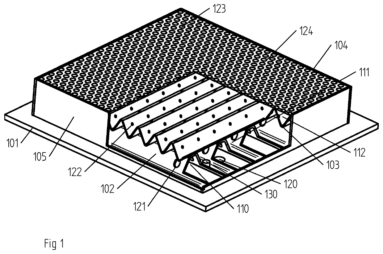
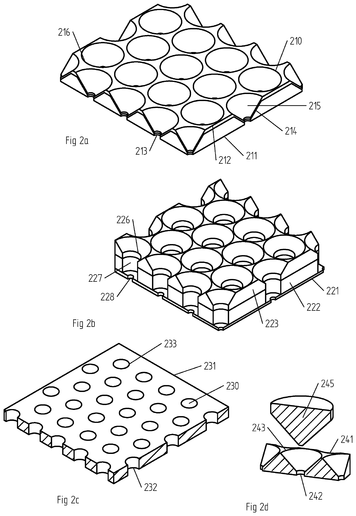
[0104]One embodiment of a viscous drag reducing cladding of the present invention is shown in FIG. 1. The top (outer) surface of the cladding comprises top sheet 104 comprising a multitude of closely-packed air pockets 124 where the diameter of the outer surface, which is adjacent to the water in the case of a ship, is larger than the inner diameter which might be adjoining the body of a ship. Pressurised air is supplied to the inside of each air pocket, and operates to keep water out of the pocket, and to eject any water that should enter the pocket. The pressurised air is supplied in this embodiment by an air distribution system comprising formed sheet metal elements 102&103 that are assembled in a way as to create air chambers 110, 111&112. Air flows from one chamber to the next via apertures in the sheets 121&122. This air distribution system provides substantially equal pressure over a large section of hull surface area or the surface area of the object to which the cladding is...


PUM


Abstract

A viscous-drag-reducing cladding for a ship's hull whereby the wetted area of the hull is reduced by interspersing air between the hull surface and the water. A substantial portion of the submerged area of the ship's hull comprises densely packed air pockets. The dimension of the air pocket is less than twice the capillary length of water. Each air pocket is supplied with pressurised gas by means of a restrictor. The pressurised air is supplied to each air pocket by means of a network of corrugated channels.

Description

FIELD OF THE INVENTION[0001]The present invention relates to the reduction of viscous drag. In particular, the present invention relates to a viscous-drag reducing cladding.BACKGROUND OF THE INVENTION[0002]The present invention is directed to the reduction of the viscous drag, such as on the hulls of ships. It is also relevant to other marine vessels and objects that travel over water, or are submerged under water such as submarines, and torpedoes. It is also relevant to cases where liquid travels through pipes or ducts or other liquid containing structures, such as in the chemical industry where liquids such as oil are pumped along pipelines. Viscous drag accounts for most of the fuel required to propel large ships. As the shipping industry is a large global producer of greenhouse gases, so reducing fuel consumption due to viscous drag will result in large reductions in environmental damage and large economic savings.[0003]Viscous drag occurs because of the phenomenon known in flui...

Claims


Application Information

Patent Timeline
IPC IPC(8): B63B1/34B63B71/00
CPCB63B71/00B63B1/34B63B2221/10B63B1/36B63B1/38B63B2001/387Y02T70/10
Inventor O'CEALLAIGH, MICHEAL
Owner OCEALLAIGH MICHEAL
Learn More