
Device and method for generating a laser pulse

a laser and laser pulse technology, applied in the direction of semiconductor lasers, using reradiation, instruments, etc., can solve the problems of inadvertent triggering of laser pulses, high transit times in the control circuit, and complicated control circuits, etc., to achieve optimal efficiency

Active Publication Date: 2020-10-08
ROBERT BOSCH GMBH
View PDF0 Cites 5 Cited by
  • Summary
  • Abstract
  • Description
  • Claims
  • Application Information

AI Technical Summary

Benefits of technology

The present invention relates to a device that generates laser pulses. The invention includes a low-resistance resistor, which helps to optimize the efficiency of the device. This means that the pump current does not have to be started an unnecessarily long time prior to emitting the laser pulse. The technical effect of this is that the device is more efficient and effective in generating laser pulses.

Problems solved by technology

It is disadvantageous that the pump area and the switch area must be controlled separately, so that complicated control circuits, for example high-side switches and low-side switches, are required.
In addition, it is disadvantageous that the transit times in the control circuit are high.
Furthermore, high rates of voltage rise during the pumping operation may result in inadvertent triggering of a laser pulse in the switch area.

Method used


Image

  • Device and method for generating a laser pulse
  • Device and method for generating a laser pulse
  • Device and method for generating a laser pulse

Examples


Embodiment Construction

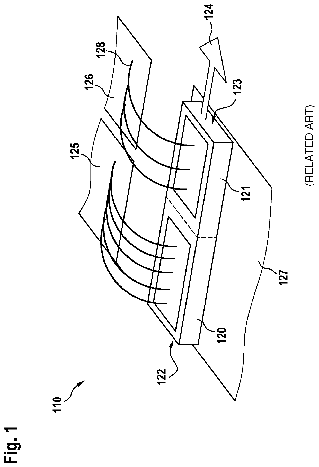
[0029]FIG. 1 shows a Q-switch laser diode from the related art that includes a controller made up of two high-side switches and a shared ground. FIG. 1 shows laser diode 110, which has a monolithic design. Laser diode 110 includes a pump area 120 and a switch area 121. Pump area 120 and switch area 121 are electrically connected to one another. The connection material may be the substrate on which laser diode 110 is situated. Pump area 120 and switch area 121 include a shared cathode 127 or ground. A highly reflective mirror 122 is situated on a short side of pump area 120. The side of the pump area opposite from highly reflective mirror 122 is directly connected to a short side of switch area 121. Switch area 121 includes a semi-reflective mirror 123, situated opposite from the short side of switch area 121, which is directly connected to pump area 120. Pump area 120 is connected with the aid of bond wires 128 to a first supply line 125 that conducts the pump current. Switch area 2...


PUM


Abstract

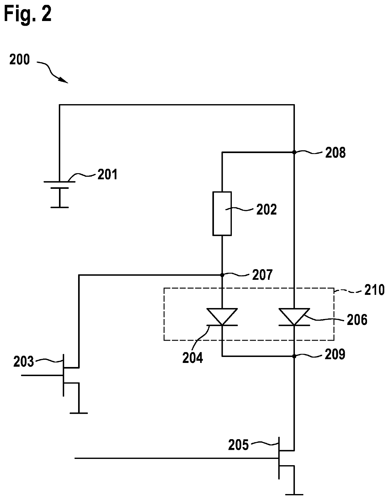
A device for generating a laser pulse. The device includes a laser diode that includes a first diode and a second diode, so that the laser diode includes a first anode, a second anode, and a cathode. The device further includes a first voltage potential that is electrically connected to the second anode, a second voltage potential that has a lower value than the first voltage potential, a first switch that is electrically connected to the first anode and to the second voltage potential, and a second switch that is electrically connected to the cathode and to the second voltage potential. A resistor is electrically connected to the first anode and to the second anode.

Description

FIELD[0001]The present invention relates to a device and a method for generating a laser pulse.BACKGROUND INFORMATION[0002]Passive and active systems are available for controlling so-called Q-switch lasers. The gain region of the lasers includes a pump area in which the energy is generated and stored, and a switch area that releases the stored energy. In passive systems, the stored energy is released when the energy in the pump area has exceeded a certain threshold value; i.e., this is a self-opening system. In active systems, the switch area is controlled by an external action, for example by opening a switch with the aid of current.[0003]It is disadvantageous that the pump area and the switch area must be controlled separately, so that complicated control circuits, for example high-side switches and low-side switches, are required. This means that special control circuits that include level adjustment and a floating supply voltage are necessary. In addition, it is disadvantageous ...

Claims


Application Information

Patent Timeline
IPC IPC(8): H01S5/042
CPCG01S7/484H01S5/0428H01S5/0615G01S17/931H01S5/06253H01S5/02216H01S5/02326H01S5/02345
Inventor PANNWITZ, AXEL
Owner ROBERT BOSCH GMBH
Learn More