System and method of using ultrafast raman spectroscopy and an ablative laser for quasi-real time removal of skin cancer and other anomalous tissues with clear tissue margins formed by array created displays

Active Publication Date: 2020-11-05
BECKMAN HUGH
View PDF0 Cites 1 Cited by
  • Summary
  • Abstract
  • Description
  • Claims
  • Application Information

AI Technical Summary

Benefits of technology

[0004]Disclosed herein is an embodiment of a medical device for diagnosing and treating anomalous tissue such as, but not limited to, basal cell carcinoma, squamous cell carcinoma, other carcinomas, atheromata and micro-organisms. Such a device comprises an energy source configured to emit at least an excitation beam of radiation such as, but not limited to, 532 nm energy as needed to produce resonance Raman scattering (RRS) at the target site. This device also comprises an energy source configured to emit at least therapeutic energy, such as, but not limited to, high-powered 10.6 micron (CO2) or low powered UVC energy as needed to produce ablation of the anomalous tissue at the target site if needed. This device also has collectors to capture the induced Raman scatter and relay it to sensors that relay the scatter energy to a spectrophotometer wherein a fingerprint is generated and relayed to a computer/controller. The fingerprint thu

Problems solved by technology

There are many disadvantages to this treatment system.
There may be unnecessary tissue removal and cosmetic damage.
Freezing the tissue samples may also be required which decrea

Method used


Image

  • System and method of using ultrafast raman spectroscopy and an ablative laser for quasi-real time removal of skin cancer and other anomalous tissues with clear tissue margins formed by array created displays
  • System and method of using ultrafast raman spectroscopy and an ablative laser for quasi-real time removal of skin cancer and other anomalous tissues with clear tissue margins formed by array created displays
  • System and method of using ultrafast raman spectroscopy and an ablative laser for quasi-real time removal of skin cancer and other anomalous tissues with clear tissue margins formed by array created displays

Examples


Example

[0020]In the various figures like reference numbers refer to identical or similar like parts. The figures are exemplary and are not drawn to scale.

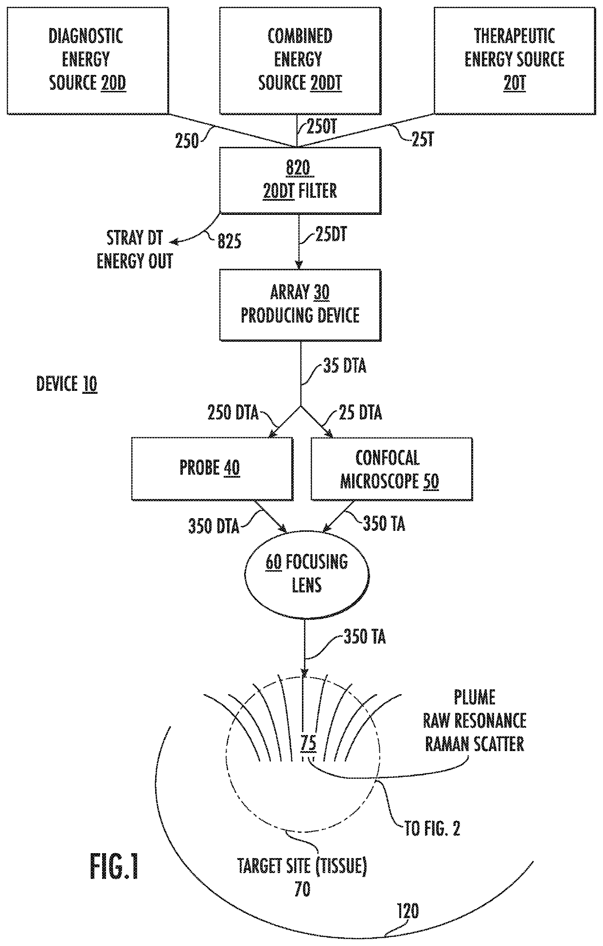
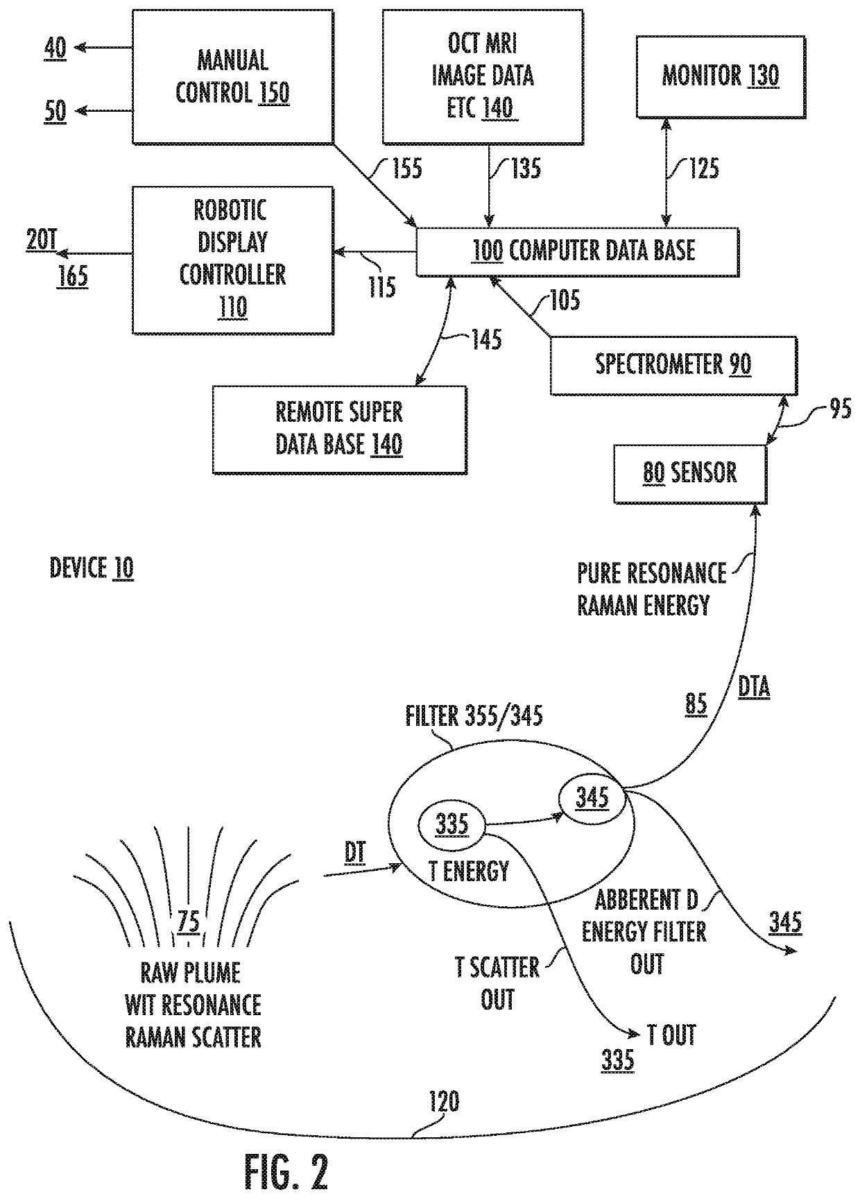
[0021]As seen in FIGS. 1 and 2 a preferred embodiment of the medical device 10 is shown for diagnosing and treating anomalous tissue. The medical device 10 comprises a high energy source 20T (therapeutic) such as but not limited to a High Peak powered CO2 laser, and a low energy source 20D (diagnostic) energy source such as, but not limited to 532 micron energy.

[0022]These energy sources are either under either the control of a manual controller 150, or a robotic display controller 110 send energy, in this embodiment, coaxially through conduit 25 DT through filter 820 to the array producing device 30 after stray energy 825 has been filtered out. The arrays formed and shown in FIGS. 4, 5, 7 and 8 continue through conduit 35 DTA to either the probe 40 or confocal microscope 50. The signals in the conduit 35DTA are focused by either delivery...


PUM


Abstract

Resonance Raman scatter is used to differentiate in quasi-real time (QRT) anomalous tissue from adjacent normal tissue. The fingerprint generated from the tissue by a 1 second pulse of 532 nm emission for approximately one second is collected and is relayed by fiber-optic to a computerized controller that determines whether the target tissue is anomalous or normal. If anomalous it is ablated. This is performed by a pattern of Resonance Raman diagnostic emission and diagnostic sensor fibers. This diagnostic/therapeutic pattern of fibers can be moved by a joystick or robotically controlled. The data received by the computer is examined instantly, and should the site be diagnosed as anomalous, the optical biopsy/ablation is repeated immediately and repeated until the site is read as normal. Novel arrays of the diagnostic and therapeutic energies ensure a 3D anomalous tissue free zone around the removal site.

Description

CROSS-REFERENCE TO RELATED APPLICATION[0001]This application is related to U.S. Provisional Application Ser. No. 61 / 051,705 filed May 9, 2008; U.S. patent application Ser. No. 12 / 437,589 filed May 9, 2008 and claims the benefit of priority of U.S. Provisional Application 62 / 920,468 filed on May 2, 2019, all of which are incorporated herein in their entirety by reference.BACKGROUND OF THE INVENTION1. Field of the Invention[0002]The present invention is generally directed to devices that analyze organic and micro-organic tissue by detecting spectra, and linking those devices to a therapeutic modality for the quasi-real-time (QRT) concurrent diagnosis and treatment of abnormal tissue, and to the process of removing the anomalous tissue, creating a zone surrounding the lesion that is free of anomalous tissue in 3D. If needed, a created template could be used to custom create a graft to facilitate repair.2. Description of the Prior Art[0003]Surgical excision of neoplastic tumor tissue, a...

Claims


Application Information

Patent Timeline
IPC IPC(8): A61B5/00A61B5/1172A61B17/3205A61B34/37A61B34/00A61L27/60G16H20/40
CPCA61B2034/742A61B5/0068A61B34/37A61B5/0075A61B2018/00577A61B5/1172A61B5/0036A61B17/3205A61B34/70G16H20/40A61B2017/00761A61B2018/00642A61B5/444A61B34/32A61L27/60G16H50/20A61B2018/00452A61B18/203A61B34/30A61B18/22A61B2018/20355A61N5/0624A61N2005/0661
Inventor BECKMAN, HUGH
Owner BECKMAN HUGH
Why Eureka
Try Eureka