
Process and device for ventilating a patient

a technology for ventilating and patient, applied in the field of process and device for ventilating a patient, can solve the problems of requiring a great deal of experience and know-how for the operation of a breathing bag, unable to ventilate adequately, etc., and achieves the effect of reducing the number of patients

Pending Publication Date: 2020-11-05
DRAGERWERK AG
View PDF3 Cites 3 Cited by
  • Summary
  • Abstract
  • Description
  • Claims
  • Application Information

AI Technical Summary

Benefits of technology

The patent is about a device / patient module that can be used to ventilate a patient automatically until a medical team reaches the scene. The device contains a special valve that controls the flow of air, and a piezo pump that can adjust the valve quickly and accurately. Multiple patient modules can be connected to a central pressure source, allowing for quick and easy ventilation of patients without the need for special training or permanent supervision. This system is cost-effective and can be easily stocked.

Problems solved by technology

However, the operation of a breathing bag requires a great deal of experience and know-how in order to supply the emergency patient with a necessary respiration rate, reasonable airway pressures and with the correct tidal volume.
Errors, which may subsequently lead to longer therapy times or even to permanent damage, may easily be made in such cases in a stress situation, which usually arises for a first responder at the location of an emergency.
Ventilators that allow an adequate ventilation are comparatively expensive and are only available, as a rule, in connection with the arriving emergency physician.
In addition, the setting and operation of such a ventilator requires at least a training and such a ventilator can therefore usually only be operated by professionally trained staff with the rapidity that is required precisely in emergency situations.
A possibly incorrectly estimated body weight value and initially used ventilation parameters, which result therefrom and which do not yet fit optimally, are thus essentially noncritical and the patient module fits the automatic ventilation independently in a physiologically meaningful manner.

Method used


Image

  • Process and device for ventilating a patient
  • Process and device for ventilating a patient
  • Process and device for ventilating a patient

Examples


Embodiment Construction

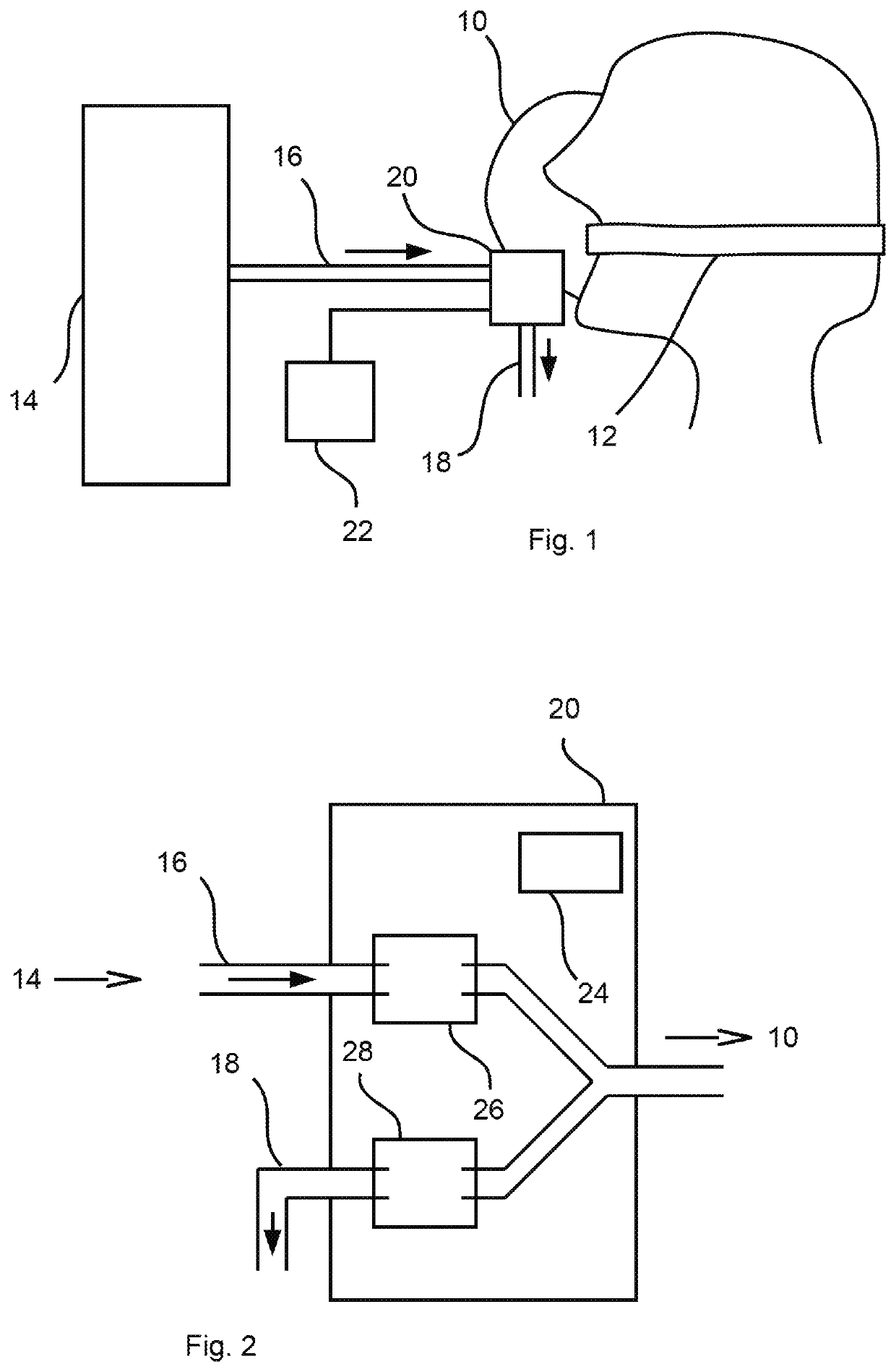
[0057]Referring to the drawings, the view in FIG. 1 shows, in a schematically highly simplified manner, a patient, who wears a breathing mask (ventilation mask) acting as a patient interface 10 for the ventilation. For example, a so-called tube (endotracheal tube) or an endotracheal cannula may also be considered, in principle, for use as a patient interface 10 instead of a breathing mask. The following description will be continued, without abandoning a further general validity, on the basis of the example of a breathing mask as a patient interface 10, which can be used incomparably more easily than a tube, since the innovation being proposed here shall also make possible, above all, the ventilation of a patient in an emergency situation, without having to presume a special experience of a first responder or the like for intubation or the like.

[0058]The patient wears the breathing mask over the mouth and nose in a manner that is basically known per se, and the breathing mask is hel...


PUM


Abstract

A process for ventilating a patient as well as a device—patient module (20)—operating according to the process, wherein, for example, a body weight value concerning an estimated body weight of the patient is transmitted to a patient module (20) intended for ventilating the patient, wherein the patient module (20) automatically selects ventilation parameters (52) fitting the body weight value on the basis of the body weight value and wherein the ventilation of the patient is carried out with the selected ventilation parameters (52).

Description

CROSS REFERENCE TO RELATED APPLICATIONS[0001]This application is a United States National Phase Application of International Application PCT / EP2018 / 076564, filed Oct. 1, 2018, and claims the benefit of priority under 35 U.S.C. § 119 of German Application 10 2017 009 602.3, filed Oct. 13, 2017, the entire contents of which are incorporated herein by reference.TECHNICAL FIELD[0002]The present invention pertains to a process for ventilating at least one patient as well as to a device intended for carrying out the process.TECHNICAL BACKGROUND[0003]Devices for ventilating a patient are, for example, ventilators or anesthesia devices. Ventilators and anesthesia devices—hereinafter summarily called ventilators or a ventilator in case of a single device—are used to provide breathing air for patients who either cannot breathe independently at all or require assistance during breathing. The patients wear for this purpose, for example, a face mask, which covers the mouth and the nose. The face...

Claims


Application Information

Patent Timeline
IPC IPC(8): A61M16/00A61M16/20A61M16/06A61M16/08A61B5/083A61B5/00A61B5/091
CPCA61M16/205A61M16/204A61M16/0066A61M2205/84A61B5/746A61M16/024A61B5/091A61M2205/8206A61M2205/52A61M2016/103A61M16/0833A61M16/0051A61M2016/0036A61M2205/078A61M2205/0294A61M2205/073A61M16/06A61M2205/609A61M16/0063A61M16/0057A61B5/0836F04B45/047F16K7/17F04B2203/0404A61M16/206A61B5/082A61B5/087F04B39/102F04B53/10G08B21/02A61M2205/07A61M2205/6018A61M2230/432A61M2016/0027A61M2205/3592A61M2205/505A61M2205/502A61M16/0072A61M2205/825A61M16/127A61M16/0078G16H40/63G16H20/40A61M2202/0225A61M2202/0014F16K31/004F16K31/1266
Inventor HANSMANN, HANS-ULLRICHHILTAWSKY, KARSTEN
Owner DRAGERWERK AG
Learn More