Flow laminator

a technology of flow stabilisation rods and laminators, which is applied in the direction of volume metering, process and machine control, instruments, etc., can solve problems such as not improving flow stability, and achieve the effect of increasing the diameter of the flow stabilisation rod

Active Publication Date: 2020-11-05
FAS MEDIC SA
View PDF0 Cites 0 Cited by
  • Summary
  • Abstract
  • Description
  • Claims
  • Application Information

AI Technical Summary

Benefits of technology

[0016]Alternatively, the diameter of the outer surface of the flow stabilisation rod may vary along the length of the flow stabilisation rod. The diameter of the outer surface may increase along the length of the flow stabilisation rod. The diameter of the outer surface may decrease along the length of the flow stabilisation rod. Where the diameter of the outer surface of the flow stabilisation rod increases along the length of the flow stabilisation rod, the diameter of the outer wall of the flow channel may decrease, stay the same, or increase in the region of the flow restriction, provided the increase in the diameter of the outer surface of the flow stabilisation rod is sufficient that the radial distance between the outer wall of the fluid flow channel and the outer surface of the flow stabilisation rod is still reduced across the flow restriction. Where the diameter of the outer surface of the flow stabilisation rod decreases along the length of the flow stabilisation rod, the diameter of the outer wall of the flow channel should also decrease such that the radial dis

Problems solved by technology

This differs from some prior art examples in which the laminar flow element is downstr

Method used


Image

  • Flow laminator
  • Flow laminator
  • Flow laminator

Examples


first embodiment

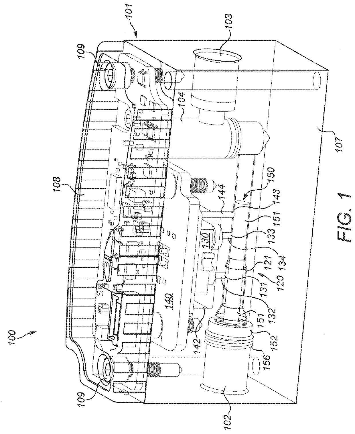
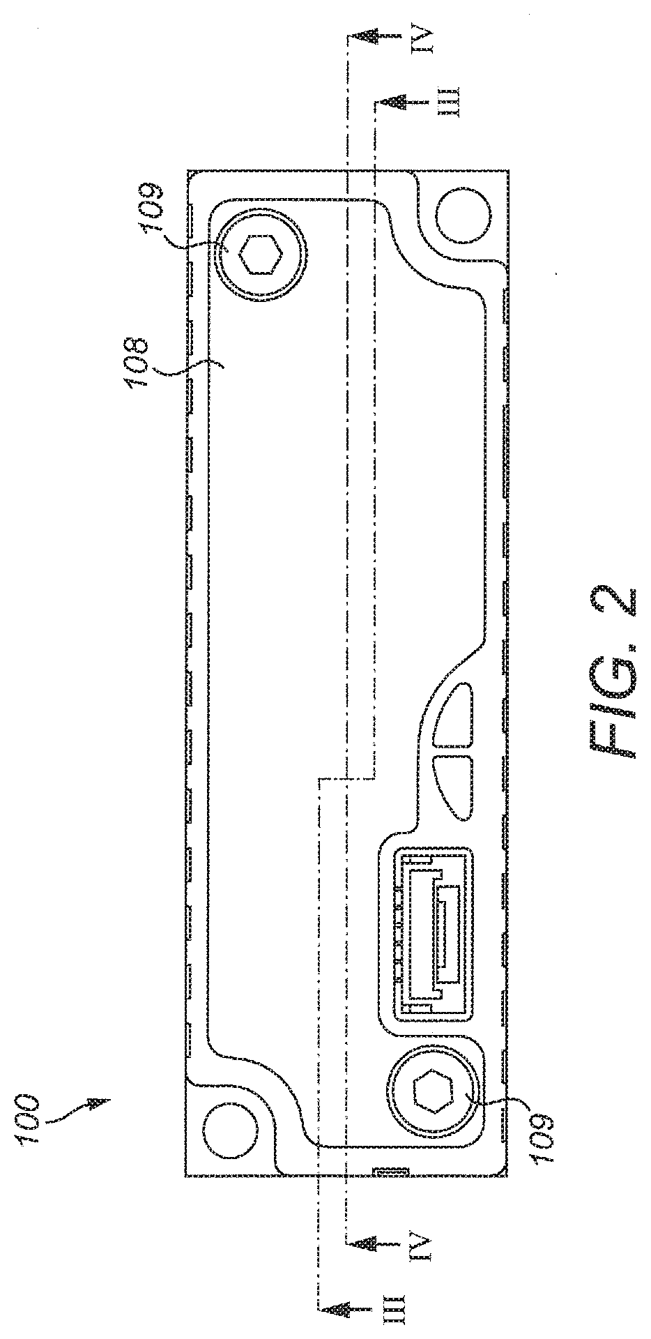
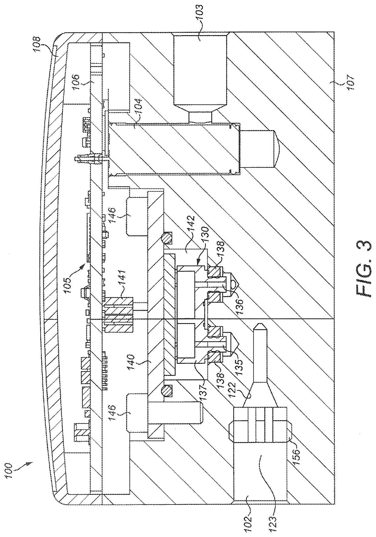
[0057]FIGS. 1 to 9 illustrate a first mass flow controller 100 including a fluid sensing apparatus 120 according to the invention. The mass flow controller 100 includes a housing 101 having a fluid inlet 102 and a fluid outlet 103. The housing 101 contains a fluid control valve 104, for example a proportional valve, and control electronics 105 mounted on a main PCB 106. In this example, the housing 101 comprises a solid body 107 and a lid 108 which is removably fixed to the solid body 107 by screws 109. The fluid control valve 104 is situated along a fluid flow path extending between the fluid inlet 102 and the fluid outlet 103 and is configured to adjust the flow rate through the mass flow controller 100, based on a control signal from the control electronics 105, in order to achieve or maintain a desired flow rate. The fluid inlet 102 and the fluid outlet 103 may be threaded, as shown in FIG. 1, to allow for easy coupling to threaded connectors.

[0058]The fluid sensing apparatus 12...

second embodiment

[0072]Further, in the mass flow controller 200 of the second embodiment, the further location 243 from which the pressure compensation port 244 extends is upstream of both of the first and second locations 231, 233, rather than downstream.

[0073]FIG. 11 shows a schematic cross-sectional view of a third embodiment of fluid sensing apparatus 320. The fluid sensing apparatus 320 includes a laminar flow element 350 having a flow stabilisation rod 351 extending along the fluid flow channel 321 from a position upstream of the first location 331 to a position downstream of the second location 333. The laminar flow element 350 is similar to the laminar flow elements 150 and 250 of the first and second embodiments of fluid sensing apparatus. However, the third embodiment of laminar flow element 350 further includes an internal flow passage 357 which extends along the length of the stabilisation rod 351. The internal flow passage 357 is in fluid communication with the channel inlet via a centr...


PUM


Abstract

There is provided a fluid sensing apparatus (120) comprising a fluid flow channel (121) having a flow restriction (125), a first fluid port (132) at a first location (131) upstream of the flow restriction, a second fluid port (134) at a second location (133) downstream of the flow restriction, a fluid sensor (130) in fluid communication with the first fluid port and second fluid port, and a laminar flow element (150). The laminar flow element includes a flow stabilisation rod (151) which extends along the fluid flow channel at least from the first location to the second location to define a fluid sensing portion of the fluid flow channel between the outer wall (122) of the fluid flow channel and the outer surface (153) of the flow stabilisation rod. The flow restriction comprises a reduction in the hydraulic diameter of the fluid sensing portion of the fluid flow channel which is caused by a decrease in diameter of the fluid flow channel, or by an increase in the diameter of the flow stabilisation rod, or by both a decrease in diameter of the fluid flow channel and an increase in the diameter of the flow stabilisation rod. Also provided is a mass flow controller (100) including such a fluid sensing apparatus.

Description

FIELD OF THE INVENTION[0001]The present invention relates to a fluid sensing apparatus and in particular to a fluid sensing apparatus for use with a fluid control valve, such as in a mass flow controller or in a mass flow meter.BACKGROUND TO THE INVENTION[0002]Fluid control valves are used in a wide variety of applications to control the flow of a fluid. The fluid being controlled may comprise a gas, a liquid, or a combination thereof. In some situations, the fluid may also include suspended particulates. While fluid control valves vary widely in the specific configuration used to open and close a fluid communication path through the valve, typically a proportional valve, one specific type of valve actuation is performed using a solenoid. In solenoid-actuated valves, an electric current passes through an electromagnetic coil, with the coil typically formed around a magnetic core. The coil generally comprises a wire that is wrapped around a bobbin numerous times resulting in a plural...

Claims


Application Information

Patent Timeline
IPC IPC(8): G01F5/00G01F1/42
CPCG01F1/42G01F5/005G01F1/88G01F15/02G01F15/04G01F15/14G01F15/005G05D7/0623G01F1/40G01F1/684G05D7/0635
Inventor AZZONI, DAVIDEDIAZ, MANUELDI DIO, JOELTANARI, VINCENT
Owner FAS MEDIC SA
Why Eureka
Try Eureka