Radio-frequency module and communication apparatus
a radio frequency module and communication apparatus technology, applied in the direction of gated amplifiers, printed circuit aspects, semiconductor/solid-state device details, etc., can solve the problems of increasing the routing length of lines and increasing propagation loss, so as to reduce the wiring propagation loss of radio-frequency signals, improve isolation, and improve isolation
- Summary
- Abstract
- Description
- Claims
- Application Information
AI Technical Summary
Benefits of technology
Problems solved by technology
Method used
Image
Examples
first embodiment
1.1 Configuration of Communication Apparatus
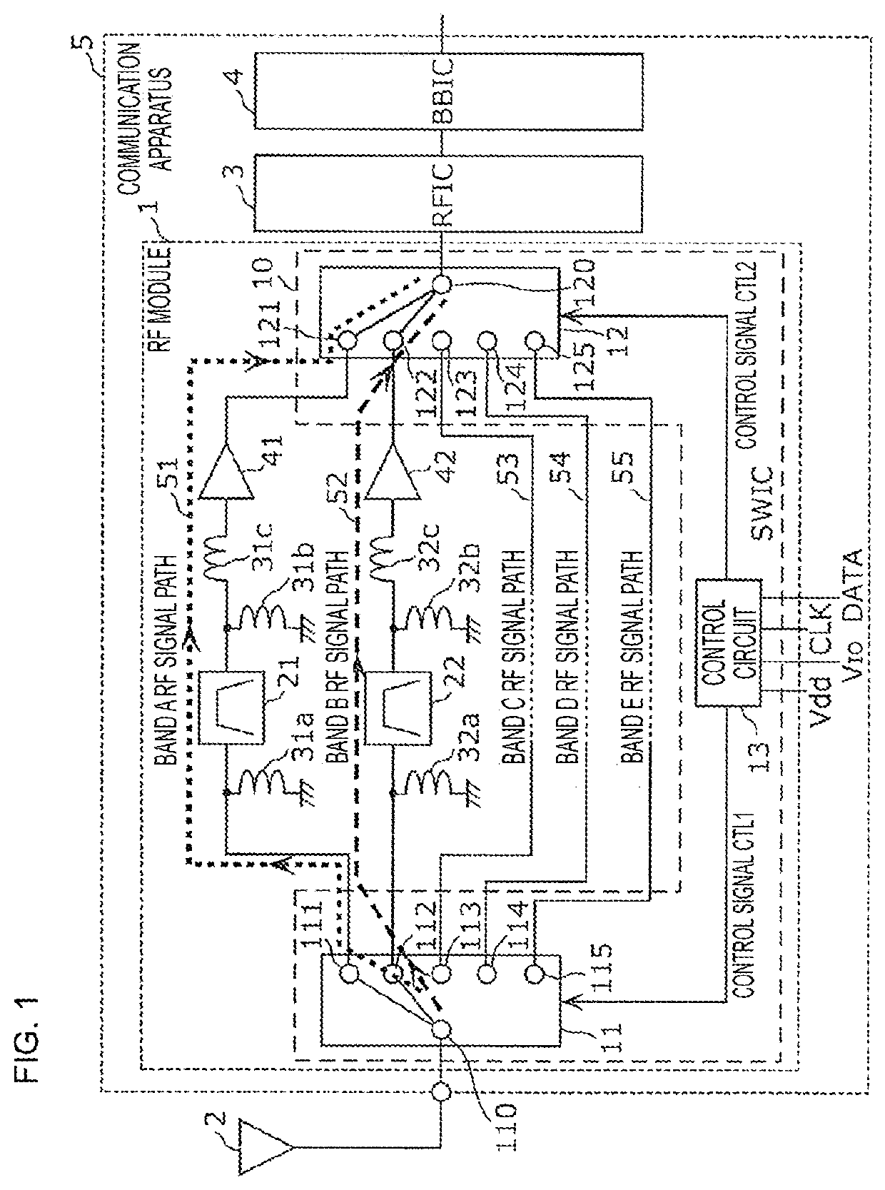
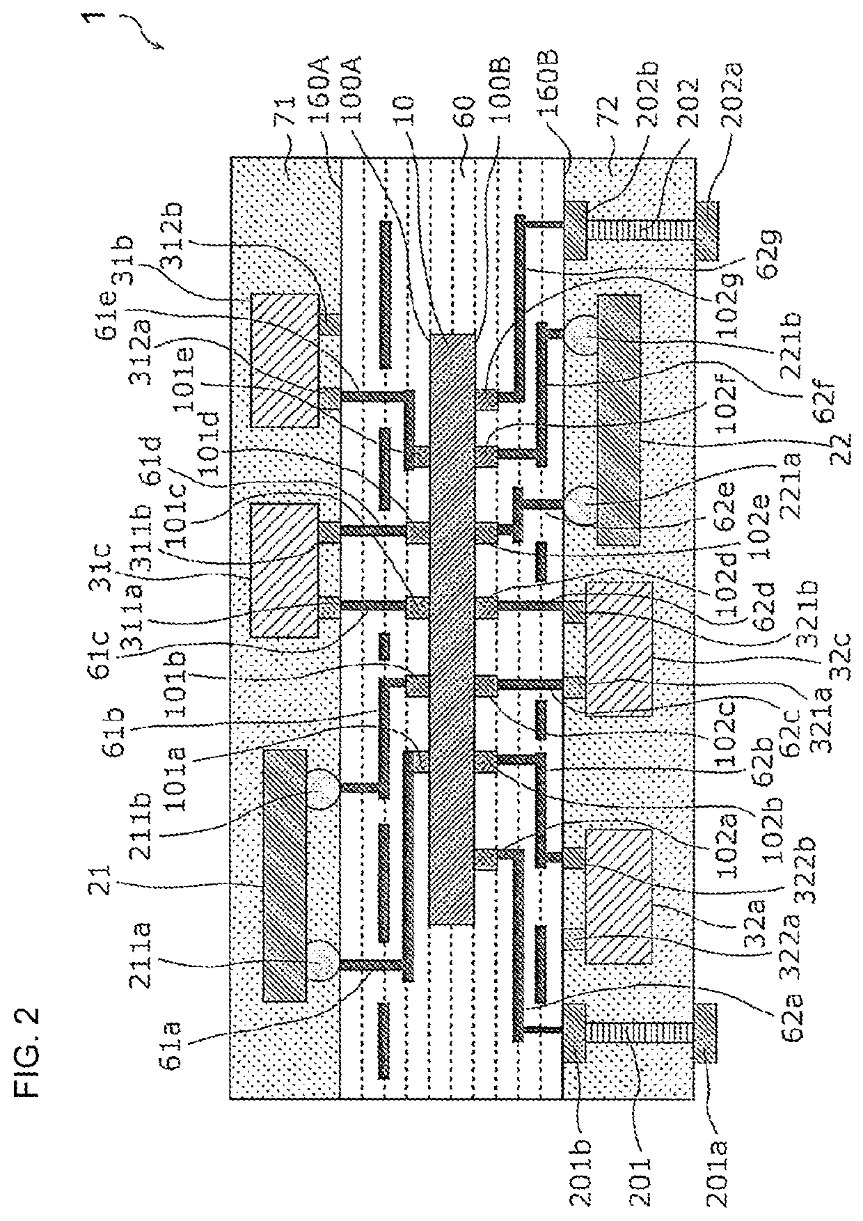
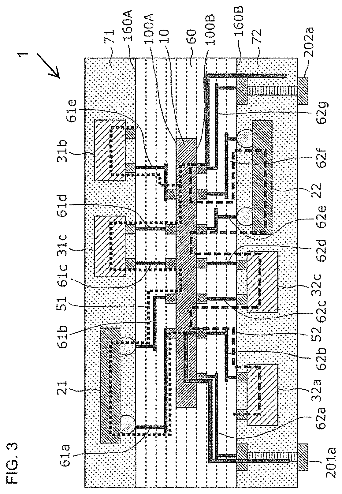
[0047]FIG. 1 is a functional block diagram of a communication apparatus 5 according to a first embodiment and peripheral circuits. The communication apparatus 5 and an antenna element 2 are illustrated in FIG. 1. The communication apparatus 5 includes a radio-frequency (RF) module 1, an RF signal processing circuit (radio-frequency integrated circuit (RFIC)) 3, and a baseband signal processing circuit (baseband integrated circuit (BBIC)) 4. The RF module 1 is arranged in, for example, a front end unit of a multimode-multiband mobile phone. The RF module 1 composes a front end circuit capable of individually or concurrently propagating a band A radio-frequency reception signal, a band B radio-frequency reception signal, a band C radio-frequency reception signal, a band D radio-frequency reception signal, and a band E radio-frequency reception signal.
[0048]The RF module 1 includes a switch IC 10, filters 21 and 22, inductors 31a, 31b, 31c, 3...
second embodiment
[0112]The switch IC is mounted in the mounting substrate in the first embodiment while an RF module in which the switch IC is surface-mounted on the mounting substrate will be described in a second embodiment. Since the circuit configuration of an RF module 1A according to the second embodiment is the same as the circuit configuration of the RF module 1 illustrated in FIG. 1, a description of the circuit configuration of the RF module 1A according to the second embodiment is omitted herein.
2.1 Structure of RF Module
[0113]The structure of the RF module 1A according to the second embodiment will now be described. FIG. 5 is a cross-sectional configuration diagram of the RF module 1A according to the second embodiment. As illustrated in FIG. 5, the RF module 1A includes the switch IC 10, mounting substrates 61 and 62, signal lines 61f, 61g, 61h, 61j, and 61k, signal lines 62h, 62j, 62k, 62m, 62n, 62p, and 62q, the filters 21 and 22, and the inductors 31b, 31c, 32a, and 32c.
[0114]The RF...
PUM
 Abstract
Description
Claims
Application Information
 - R&D
- Intellectual Property
- Life Sciences
- Materials
- Tech Scout
- Unparalleled Data Quality
- Higher Quality Content
- 60% Fewer Hallucinations
Browse by: Latest US Patents, China's latest patents, Technical Efficacy Thesaurus, Application Domain, Technology Topic, Popular Technical Reports.
© 2025 PatSnap. All rights reserved.Legal|Privacy policy|Modern Slavery Act Transparency Statement|Sitemap|About US| Contact US: help@patsnap.com


