Radio frequency module

a frequency module and radio frequency technology, applied in the field of radio frequency modules, can solve the problem of relativly difficult control of the loop shape on the second bond side, and achieve the effects of reducing the distance between the bonding wire and the component, increasing the shielding performance, and high density

Active Publication Date: 2020-11-19
MURATA MFG CO LTD
View PDF0 Cites 2 Cited by
  • Summary
  • Abstract
  • Description
  • Claims
  • Application Information

AI Technical Summary

Benefits of technology

[0025]With this configuration, since the bonding wire is connected with the shield film, shield performance as a compartment shield can be further increased.
[0026]With the present disclosure, since the bonding ending-point portion of the bonding wire is connected to the protruding electrode, the loop shape on the second bond side can be controlled. A shield member can be formed without necessarily a contact with the component. Moreover, since the distance between the bonding wire and the component can be decreased by controlling the loop shape using the protruding electrode, components can be mounted with high density, and the degree of freedom in design can be increased.

Problems solved by technology

This is because, in a wire bonding technology, it is relatively easy to control the loop shape on a first bond side that is a wire starting-point side; however, it is relatively difficult to control the loop shape on the second bond side.
The reason why controlling the loop shape on the second bond side is difficult is because it is difficult to bend the wire and dispose the wire at a position close to the component and the loop shape of the wire is required to be an extended end shape on the second bond side, and hence the wire ending point has to be set at a position far from the component.

Method used


Image

  • Radio frequency module
  • Radio frequency module
  • Radio frequency module

Examples


first embodiment

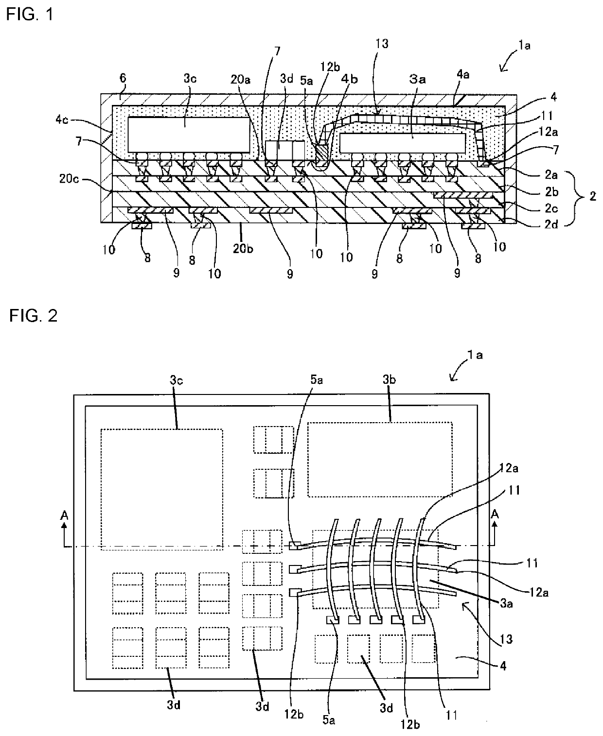
[0038]A radio frequency module 1a according to a first embodiment of the present disclosure is described with reference to FIGS. 1 and 2. FIG. 1 is a cross-sectional view taken along line A-A in FIG. 2. FIG. 2 is a plan view of the radio frequency module 1a in a state without necessarily a shield film 6.

[0039]As illustrated in FIGS. 1 and 2, the radio frequency module 1a according to this embodiment includes a multilayer wiring board 2 (corresponding to “a wiring board” according to the present disclosure), a plurality of components 3a to 3d mounted on an upper surface 20a of the multilayer wiring board 2, a sealing resin layer 4 stacked on the upper surface 20a of the multilayer wiring board 2, a shield film 6 that covers a surface of the sealing resin layer 4, a plurality of first protruding electrodes 5a mounted on the upper surface 20a of the multilayer wiring board 2, and a bonding wire 11 disposed to straddle the component 3a. For example, the radio frequency module 1a is moun...

second embodiment

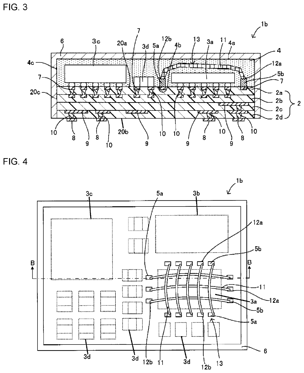
[0052]A radio frequency module 1b according to a second embodiment of the present disclosure is described with reference to FIGS. 3 and 4. FIG. 3 is a cross-sectional view of the radio frequency module 1b and is a cross-sectional view taken along line B-B in FIG. 4. FIG. 4 is a plan view of the radio frequency module 1b in a state without necessarily the shield film 6.

[0053]The radio frequency module 1b according to this embodiment differs from the radio frequency module 1a according to the first embodiment described with reference to FIGS. 1 and 2 in that, as illustrated in FIGS. 3 and 4, each of a plurality of second protruding electrodes 5b is disposed at a bonding starting-point portion 12a (an end portion on a first bond side) of the bonding wire 11. The other configuration is similar to that of the radio frequency module 1a of the first embodiment. The same reference sign is applied to the same component and the redundant description is omitted.

[0054]In this embodiment, each s...

third embodiment

[0060]A radio frequency module 1e according to a third embodiment of the present disclosure is described with reference to FIGS. 7 and 8. FIG. 7 is a cross-sectional view of the radio frequency module 1e and is a cross-sectional view taken along line C-C in FIG. 8. FIG. 8 is a plan view in a state without necessarily the shield film 6 in FIG. 7.

[0061]The radio frequency module 1e according to this embodiment differs from the radio frequency module 1a according to the first embodiment described with reference to FIGS. 1 and 2 in that, as illustrated in FIGS. 7 and 8, a plurality of bonding wires 11b are disposed along the periphery of the component 3a to surround the component 3a when viewed in the direction perpendicular to the upper surface 20a of the multilayer wiring board 2. The other configuration is similar to that of the radio frequency module 1a of the first embodiment. The same reference sign is applied to the same component and the redundant description is omitted.

[0062]In...


PUM


Abstract

A radio frequency module in which the loop shape of a wire can be stable by disposing a protruding electrode at a bonding ending-point portion when a bonding wire forms a shield between components is provided. A radio frequency module includes a multilayer wiring board, components to mounted on an upper surface of the multilayer wiring board, a shield member formed of a plurality of bonding wires to cover the component, and a protruding electrode provided at a bonding ending-point portion of each of the bonding wires. Since the protruding electrode is provided at the bonding ending-point portion of each of the bonding wires, undesired bending can be prevented on a second bond side of the bonding wire. The shield member to cover side surfaces and a top surface of the component can be easily formed.

Description

[0001]This is a continuation of International Application No. PCT / JP2019 / 003966 filed on Feb. 5, 2019, which claims priority from Japanese Patent Application No. 2018-020691 filed on Feb. 8, 2018. The contents of these applications are incorporated herein by reference in their entireties.BACKGROUNDTechnical Field[0002]The present disclosure relates to a radio frequency module including a shield.[0003]A motherboard of an electronic device, such as a communication terminal device has mounted thereon various radio frequency modules. Such radio frequency modules include a radio frequency module in which a component mounted on a wiring board is sealed with a sealing resin layer. Moreover, the surface of the sealing resin layer may be covered with a shield film to shield the component from noise. When a plurality of components are mounted on a wiring board, only a specific component may be desired to be shielded from noise. However, it is difficult to shield only the specific component fr...

Claims


Application Information

Patent Timeline
Patent Type & Authority Applications(United States)
IPC IPC(8): H01L23/14H01Q1/52H01Q23/00
CPCH01L2924/181H01L2224/16225H01Q1/526H01L2924/19107H01L2924/19105H01L23/142H01Q23/00H01L2224/48227H05K9/00H01L23/552H01L23/5386H01L23/49811H01L23/3121H01L2924/3025H01L25/0655H01L25/16H01L24/16H01L24/13H01L2224/16227H01L2924/1421H01L2224/131H01L2924/00012H01L2924/014
Inventor OTSUBO, YOSHIHITOMORIMOTO, YUTA
Owner MURATA MFG CO LTD
Why Eureka
Try Eureka