
Basket-type ep catheter with electrode polling for sequential electrode sampling

a catheter and electrode technology, applied in the field of medical devices, can solve the problems of depolarization waves, atrial arrhythmias can create a variety of dangerous conditions, irregular heart rate, loss of synchronous atrioventricular contraction, etc., and achieve the effect of allowing for other structures or lumens to be sampled

Pending Publication Date: 2020-12-10
LAKE REGION MFG
View PDF4 Cites 0 Cited by
  • Summary
  • Abstract
  • Description
  • Claims
  • Application Information

AI Technical Summary

Benefits of technology

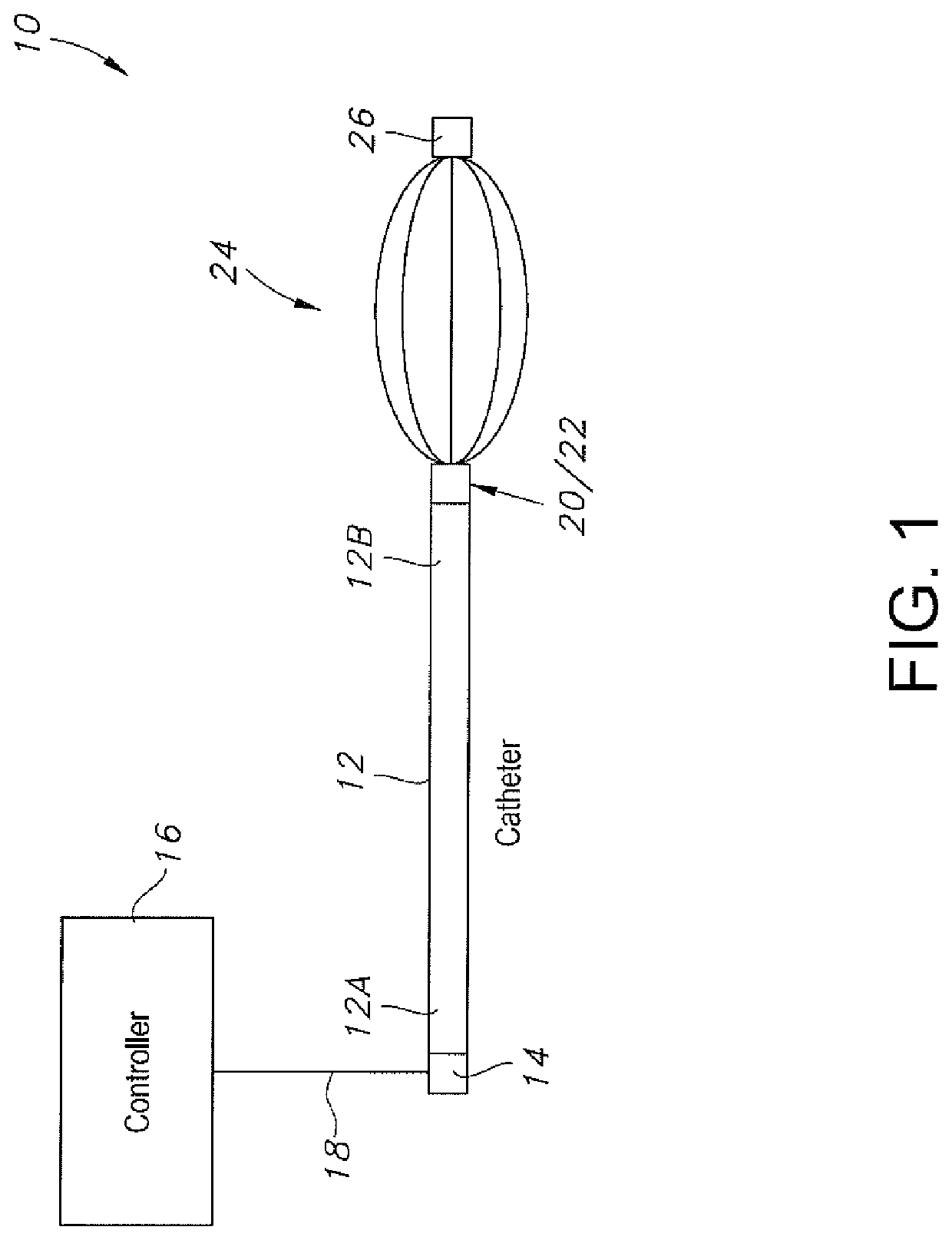
The invention is a catheter that uses a single conductor to take voltage samples from multiple electrodes. This reduces the number of conductors needed, making it possible to have other features or lumens in the catheter. The electrodes are connected to a one-shot circuit and a signal pass-transistor or transmission gate to allow for sequential sampling. This design is advantageous over existing basket-type catheters.

Problems solved by technology

These obstacles may cause depolarization waves to electrically circulate through some parts of the heart more than once.
Atrial arrhythmia can create a variety of dangerous conditions, including irregular heart rates, loss of synchronous atrioventricular contractions, and blood flow stasis.
The lesioned tissue is less capable of conducting electrical signals, thereby disrupting undesirable electrical pathways and limiting or preventing stray electrical signals that lead to arrhythmias.
Not only is having a dedicated Vout conductor for each electrode in a spline system complicated and difficult to construct, it does not much leave room in the catheter shaft for other structure, such as a delivery lumen, a suction lumen, a fiber optic cable, pull wires, and the like.

Method used


Image

  • Basket-type ep catheter with electrode polling for sequential electrode sampling
  • Basket-type ep catheter with electrode polling for sequential electrode sampling
  • Basket-type ep catheter with electrode polling for sequential electrode sampling

Examples


Embodiment Construction

[0030]As used herein, the terms “sampling sequence”, “consecutive electrode sampling sequence” and “consecutively sampling” mean that the electrodes on a spline or a number of splines forming a spline system are sampled in a consecutive manner with a second or next electrode being sampled following sampling of a first electrode or an electrode located immediately before the second electrode without interruption.

[0031]Commercially available basket-type EP catheters have many electrodes. For example, there are basket-type EP catheters that have eight electrodes on eight splines for a total of 64 electrodes or 16 electrodes on eight splines for a total of 128 electrodes. Conventional systems require a separate voltage-out (Vout) conductor for each electrode. The dedicated Vout conductor passes voltage from an electrode to signal analysis hardware connected to the proximal end of the catheter. This means that there is a separate Vout conductor connected to each electrode of a spline and...


PUM


Abstract

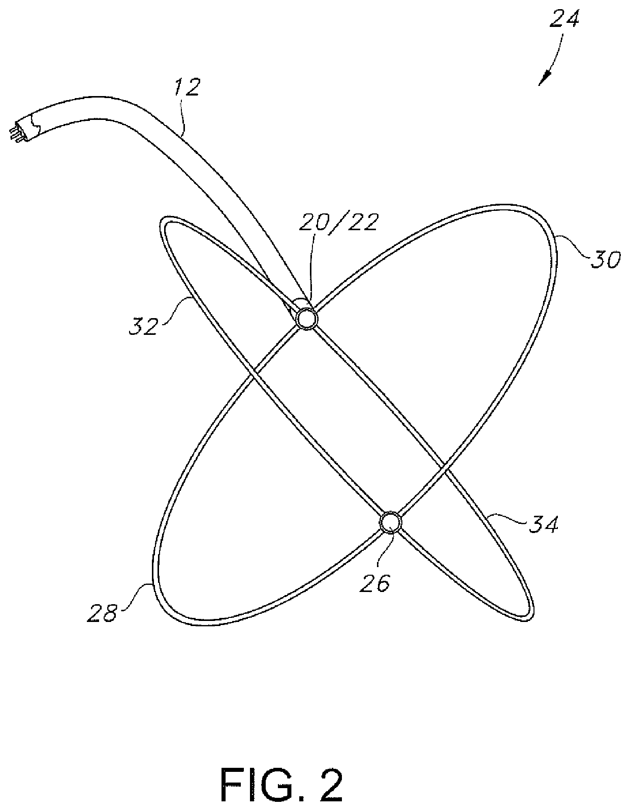
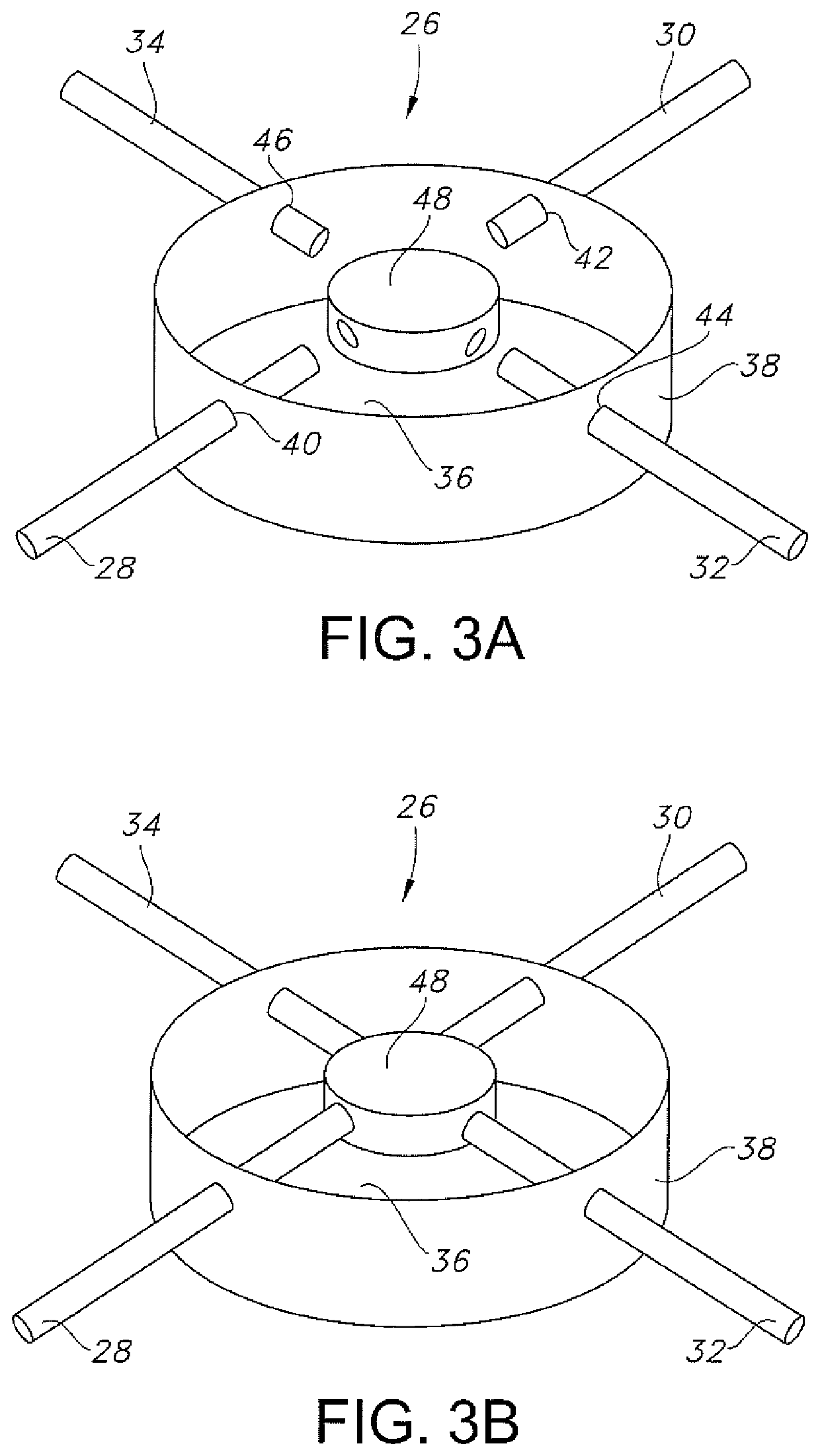
A basket-type EP catheter is described. The EP catheter comprises a catheter proximal end that is electrically connected to a controller by an electrical cable having a single voltage-out (Vout) conductor and a catheter distal end supporting a distal connector that is detachably connectable to a basket-shaped configuration of a plurality of splines. Each spline supports an array of electrodes. By sampling the voltage signal on each of the plurality of electrodes sequentially or consecutively, only one Vout conductor is needed to transmit the voltage sample to the controller. In comparison to conventional EP catheters, this greatly reduces the number of conductors extending along the catheter shaft. The use of a Vout conductor is implemented by connecting a polling circuit or a “one-shot” circuit and a signal pass-transistor or transmission gate to each electrode.

Description

CROSS-REFERENCE TO RELATED APPLICATION[0001]This application claims priority to U.S. Provisional Application Ser. No. 62 / 858,375, filed on Jun. 7, 2019.BACKGROUND OF THE INVENTION1. Field of the Invention[0002]The present invention relates to the field of medical devices. More specifically, the present invention is directed to determining and representing anatomical and physiological information related to a heart using a contact catheter.2. Prior Art[0003]The human heart routinely experiences electrical impulses traversing its many surfaces and ventricles, including the left atrium. Just prior to each heart contraction, the heart depolarizes and repolarizes as electrical currents spread across the heart and throughout the body. In healthy hearts, the surfaces and ventricles of the heart experience an orderly progression of depolarization waves. In unhealthy hearts, such as those experiencing atrial arrhythmia, including for example, ectopic atrial tachycardia, atrial fibrillation, ...

Claims


Application Information

Patent Timeline
IPC IPC(8): A61B5/0428A61B5/042A61B5/00A61B5/308
CPCA61B5/0422A61B2562/0209A61B5/04282A61B5/6858A61B5/04284A61B2018/00267A61B2018/00351A61B2018/00577A61B2018/00839A61B18/1492A61B2018/0212A61B18/02A61B18/20A61N7/02A61B2218/002A61B2218/007A61B2562/225A61B2562/04A61B2018/00178A61B5/287A61B5/302A61B5/301
Inventor HAYES, JOHN MICHAEL
Owner LAKE REGION MFG
Learn More