Thin film fluopolymer composite cmp polishing method

Active Publication Date: 2020-12-10
ROHM & HAAS ELECTRONICS MATERIALS CMP HLDG INC
View PDF0 Cites 0 Cited by
  • Summary
  • Abstract
  • Description
  • Claims
  • Application Information

AI Technical Summary

Benefits of technology

This patent describes a method for polishing or planarizing semiconductor, optical, and magnetic substrates using a special polymer-polymer composite polishing pad. The pad has a layers of polishing material made of a polymer matrix with embedded fluoropolymer particles. The method involves applying a slurry containing cationic particles to the pad, conditioning it with an abrasive to cut the pad, and rubbing it against the substrate to create a polishing surface with a high concentration of fluorine. This results in a more effective polishing process with improved polish quality.

Problems solved by technology

This leads to a high rate of relative motion between the wafer and the polishing pad (i.e., there is a high rate of shear at both the substrate and the pad surface.
This yields undesirably lengthy CMP process times for the PMD step, which now is the primary bottleneck in the 3D NAND manufacturing process.

Method used


Image

  • Thin film fluopolymer composite cmp polishing method
  • Thin film fluopolymer composite cmp polishing method
  • Thin film fluopolymer composite cmp polishing method

Examples


example 1

[0069]The physical properties of a set of Sample A made with and without the addition of 10 weight percent of PTFE-1 and PFA were conducted. As shown in the Table below, changes of note were the reduction in tensile strength, hardness and the majority of the mechanical properties. Of specific interest was the difference in the effect of additions on the shear storage modulus (G′), which was characteristic of elastic behavior versus the effect on the shear loss modulus (G″), which represents the amount of energy dissipated in the sample. Shear storage modulus G′ at 40° C. showed a significant reduction relative to the control (−31% for PFA and −45% for PTFE). Shear loss modulus, G″ showed a similar trend (−26% for PFA and −37% for PTFE). While all samples were primarily elastic polymers, tan 6, the ratio of G″ to G′, increased by 6% and 14% for PFA and PTFE additions, respectively. This was a direct measure of the increase in the energy dissipation effected by the fluoropolymer addit...

example 2

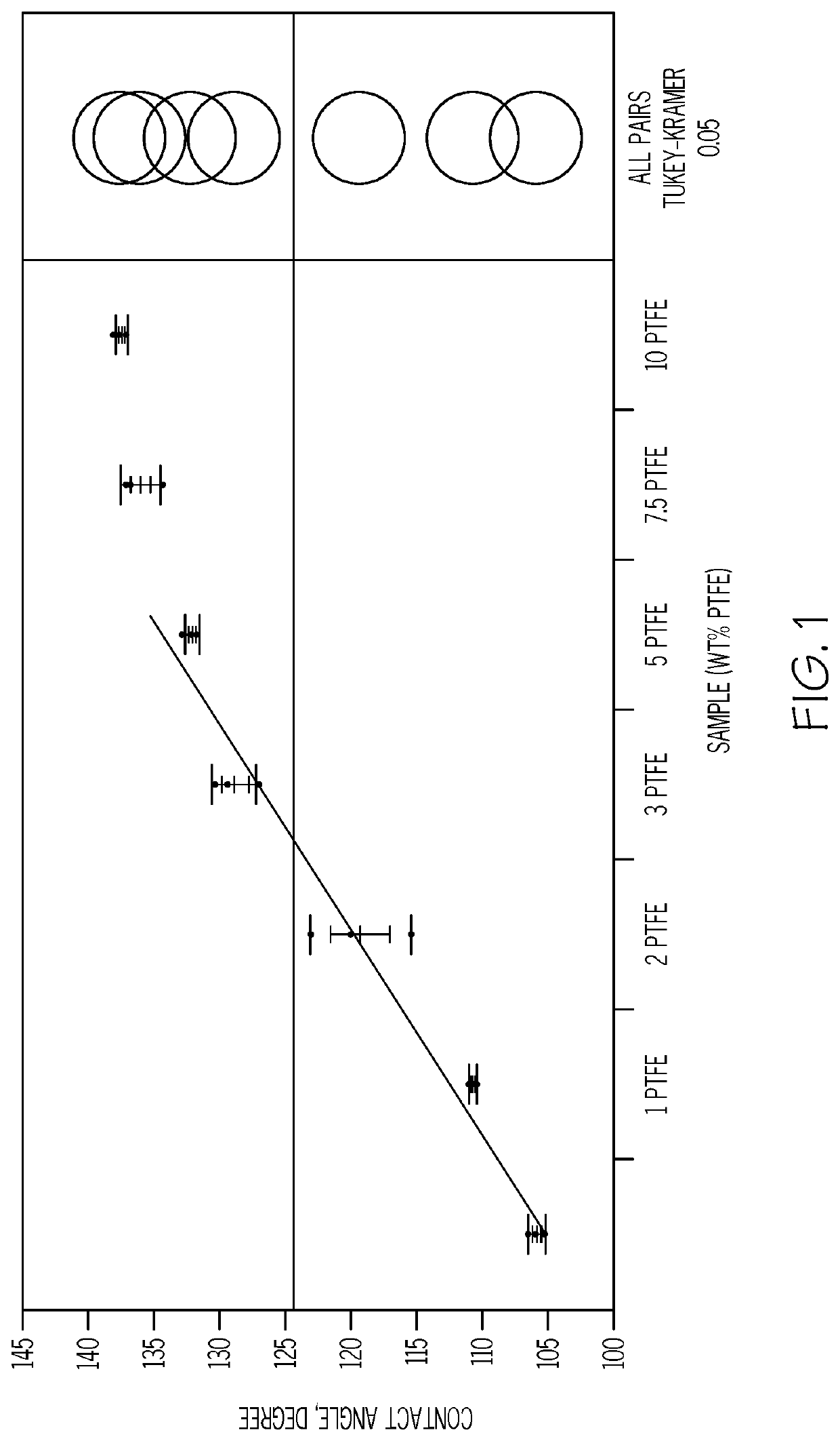
[0072]The deionized water contact angle was measured on a set of medium porosity polyurethane pads of Sample B that had varying amounts of PTFE-2 added during manufacturing. As shown in FIG. 1, the contact angle increased directly with increasing PTFE content to a steady state value of around 140 degrees by 7.5% PTFE content. All pads with both PTFE and PFA additions were visibly more hydrophobic than the parent pad. Despite this, the polishing surface is hydrophilic as measured with distilled water at a pH of 7 at a surface roughness of 10 μm rms after soaking in distilled water for five minutes.

example 3

[0073]A polishing test was performed on a set of high-strength Sample A pads with and without the addition of PTFE and PFA in order to demonstrate the beneficial effects of the present invention. The concentration of each fluoropolymer added was 8.1%. Three slurries were tested on each pad set using 60 200 mm TEOS monitor wafers per test on an Applied Materials Mirra CMP polishing tool. The slurries used were two ceria slurries (Asahi CES333F2.5 and DA Nano STI2100F) and a fumed silica slurry (Cabot SS25). Conditions used were 3 psi (20.7 kPa) downforce, 93 rpm platen speed, 87 rpm carrier speed, and 150 ml / minute slurry flow. Conditioners varied by slurry type. For the ceria slurries, a Saesol LPX-C4 diamond conditioner disk was used. For the silica slurry, a Saesol AK45 conditioner disk was used. All conditioners were used concurrently with polishing at 7 lb force (3.2 kgf). For each run, a pad break-in conditioning step was used for 20 minutes at 7 lb force (3.2 kgf) to ensure a ...


PUM

PropertyMeasurementUnit
Lengthaaaaaaaaaa
Fractionaaaaaaaaaa
Fractionaaaaaaaaaa

Abstract

The invention provides a polymer-polymer composite polishing method comprising a polishing layer having a polishing surface for polishing or planarizing a substrate. The method includes attaching a polymer-polymer composite having a polishing layer and a polymeric matrix. The polymer matrix has fluoropolymer particles embedded in the polymeric matrix. Then a cationic particle slurry is applied to the polymer-polymer composite polishing pad. Conditioning the polymer-polymer composite polishing pad with an abrasive cuts the polymer-polymer composite polishing pad; and rubbing the cut polymer-polymer composite polishing pad against the substrate forms the polishing surface. The polishing surface has a fluorine concentration measured in atomic percent at a penetration depth of 1 to 10 nm of at least ten percent higher than the bulk fluorine concentration measured with at a penetration depth of 1 to 10 μm to polish or planarize the substrate.

Description

BACKGROUND OF THE INVENTION[0001]Chemical Mechanical Planarization (CMP) is a variation of a polishing process that is widely used to flatten, or planarize, the layers of construction of an integrated circuit in order to precisely build multilayer three dimensional circuitry. The layer to be polished is typically a thin film (less than 10,000 Angstroms) that has been deposited on an underlying substrate. The objectives of CMP are to remove excess material on the wafer surface to produce an extremely flat layer of a uniform thickness, the uniformity extending across the entire wafer. Control of removal rate and the uniformity of removal are of paramount importance.[0002]CMP utilizes a liquid, often called slurry, which contains nano-sized particles. This is fed onto the surface of a rotating multilayer polymer sheet, or pad, which is mounted on a rotating platen. Wafers are mounted into a separate fixture, or carrier, which has a separate means of rotation, and pressed against the su...

Claims


Application Information

Patent Timeline
IPC IPC(8): B24B37/04B24B37/24H01L21/306C08L75/04C09G1/02
CPCB24B37/044B24B37/24H01L21/30625C08L2205/14C09G1/02C08L2205/03C08L2205/025C08L75/04C08G18/10C08G18/4825C08G18/4854C08G18/7621C08G18/7671C09D175/08H01L21/31053C08L27/18
Inventor ISLAM, MOHAMMAD T.CHIOU, NAN-RONGGADINSKI, MATTHEW R.PARK, YOUNGRAEBLACKMAN, GREGORY SCOTTZHANG, LEIJACOB, GEORGE C.
Owner ROHM & HAAS ELECTRONICS MATERIALS CMP HLDG INC
Why Eureka
Try Eureka