Sensor

a technology of sensors and sensors, applied in the field of sensors, can solve the problems of poor vibration reduction capability of existing sensor systems, and achieve the effects of ensuring the reliability of detecting elements and sensors, and reducing the vibration displacement of detecting elements

Inactive Publication Date: 2020-12-10
SUZHOU EV BLUE ELECTRONICS TECH CO LTD
View PDF0 Cites 1 Cited by
  • Summary
  • Abstract
  • Description
  • Claims
  • Application Information

AI Technical Summary

Benefits of technology

[0031]When external environment produces mechanical shock to the sensor or the sensor produces mechanical vibration, the external mechanical shock can be partially or completely absorbed by the first cylinder with an amount of elastic deformation and the particle filler, so as to reduce vibration displacement of the detecting element caused by the shock; meanwhile, the first cylinder and the particle filler have a limiting action on the detecting element such that the vibration displacement amount of the detecting element is buffered and absorbed, thereby enabling the detecting element to only have very little vibration displacement or even no vibration displacement relative to the housing. Because the detecting element has very little vibration displacement or even no vibration displacement relative to the housing, the connection portion of a pin of the detecting element would not receive too much force to cause breaking off or splitting, so that a function failure of the sensor due to mechanical vibration or external mechanical shock is prevented, and the reliability of the detecting element and the sensor is ensured.
[0032]As the detecting element has a small volume and a light mass, during installation by welding, the detecting element may deviate towards one lateral side of the housing or even come into contact with an inner wall of the housing. The first cylinder can guide the detecting element during installation and correct any offset angle of the detecting element, thereby holding the detecting element in a central position in a radial direction of the housing, so that the detecting element is prevented from strong impact with the inner wall of the housing during operation due to offset shifting which would ultimately cause splitting of a pin of the detecting element.
[0033]The sealing element is closely compressed between the second cylinder and the third cylinder, so as to be able to form an effective sealing and prevent external substance such as liquid or gas from entering the third cylinder to cause a function failure of the sensor.

Problems solved by technology

Thus, a technical problem to be solved by the present application is that the existing sensor system has poor capability of vibration reducing.

Method used


Image

  • Sensor
  • Sensor
  • Sensor

Examples


embodiment 1

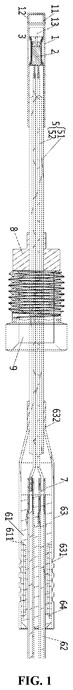
[0071]This embodiment provides a sensor, as shown in FIG. 1, the sensor comprises a housing 1, a cap 12, a detecting element 2, a first cylinder 3, a particle filler (not shown), a transmitting cable 5, a connector 7, a wiring harness component, a flange 8 and a screw nut 9.

[0072]Wherein, the transmitting cable 5 is preferably a mineral insulation cable and comprises a conductive line 52, a metal sheath 51 sleeved outside the conductive line 52, and inorganic insulation material or an inorganic insulation material layer filled inside the metal sheath 51 and surrounding the conductive line 52. The transmitting cable 5 has good high-temperature resistance and is able to transmit signal in a high-temperature environment. There are preferably two conductive lines 52.

[0073]The detecting element 2 is preferably a temperature sensing element, and two pins of the temperature sensing element are fixedly connected by welding to two conductive lines 52 at one end of the transmitting cable 5, a...

embodiment 2

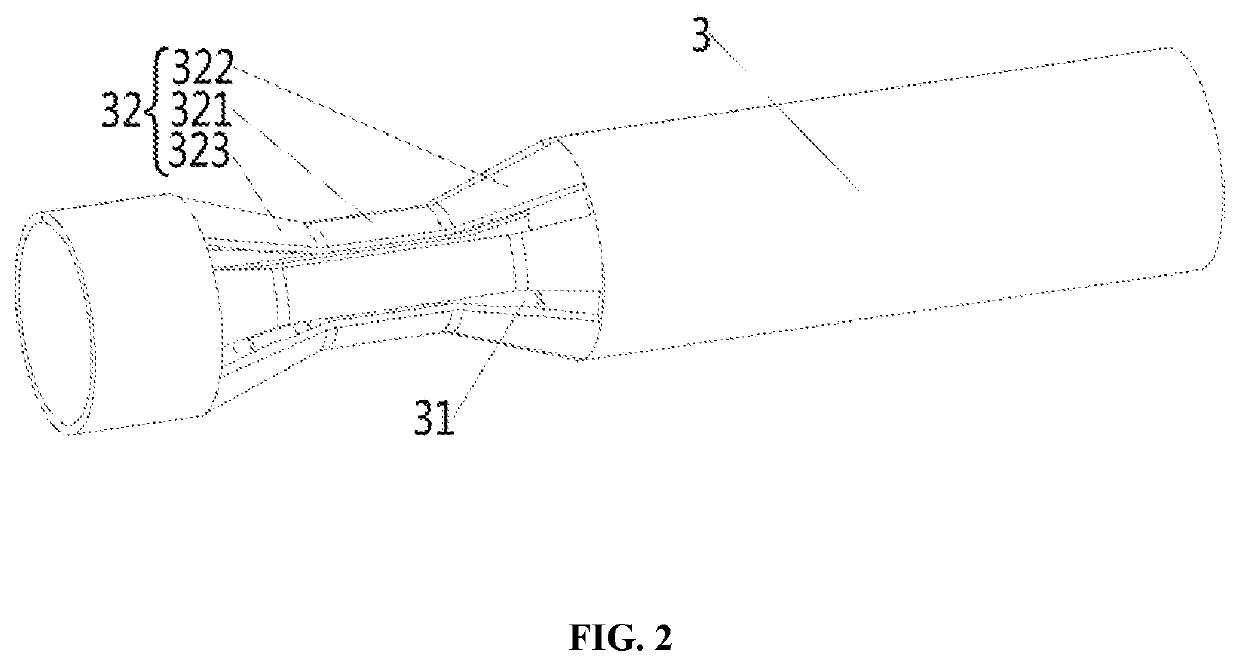
[0092]This embodiment provides a sensor, the structure of which differs that of the sensor of Embodiment 1 in that the first cylinder 3 has a different structure, as shown in FIG. 6 and FIG. 7, the first cylinder 3 has a U-shaped symmetrical structure, the hollow part of the U-shaped structure forms a through-hole 31, and the temperature sensing element is inserted in the through-hole 31.

[0093]A portion of the first cylinder 3 right facing the temperature sensing element is recessed inward to form a recessed region 32 which has two symmetrical sides, each side of the recessed region 32 comprises a first segment 321, a first flared segment 322 and a second flared segment 323 that are integrally formed in one piece; the first segment 321 is a straight segment extending along an axial direction of the housing 1, the first flared segment 322 and the second flared segment 323 are respectively connected to both ends of the first segment 321 and extend outward at a certain angle away from ...

embodiment 3

[0096]This embodiment provides a sensor, the structure of which differs from that of the sensor of Embodiment 2 in that the recessed region 32 may only comprise a straight first segment 321 and a first flared segment 322 and / or may only comprise a straight first segment 321 and a second flared segment 323.

[0097]Furthermore, as shown in FIG. 8, FIG. 9 and FIG. 10, herein, the recessed region 32 only comprise a first segment 321 and a first flared segment 322, there is a certain distance from the first flared segment 322 to an inner wall of the housing 1; the first segments 321 at both sides are connected by a curved transition structure, and one end of the first cylinder 3 away from the transmitting cable 5 is likewise provided with a buffering hole 33.

[0098]The housing 1 comprises a contraction section 14 and a sealed section 15. The portion of the housing all the way from a location corresponding to the first segment 321 to its end part at an end away from the transmitting cable 5 ...


PUM

PropertyMeasurementUnit
elastic deformationaaaaaaaaaa
elasticaaaaaaaaaa
heat conductiveaaaaaaaaaa

Abstract

Disclosed is a sensor, comprising: a housing; a detecting element provided inside the housing; a first cylinder provided inside the housing and sleeved outside the detecting element, the first cylinder having an amount of elastic deformation in a direction intersecting a surface around the detecting element; a particle filler, for filling an inner cavity of the housing. When external environment produces mechanical shock to the sensor or the sensor produces mechanical vibration, the limiting action of the first cylinder and the particle filler enables the detecting element to only have very little vibration displacement or even no vibration displacement with respect to the housing. The external mechanical shock can be partially or completely absorbed by the first cylinder and the particle filler, so as to reduce vibration displacement of the detecting element caused by the shock.

Description

CROSS REFERENCE TO RELATED APPLICATIONS[0001]This application is a continuation of International Application No. PCT / CN2019 / 082478, filed on Apr. 12, 2019, which is based upon and claims priority to Chinese Patent Application No. 2018205534314, filed on Apr. 18, 2018, the entire contents of which are incorporated herein by reference.TECHNICAL FIELD[0002]The present application belongs to the technical field of sensors, and particularly relates to a sensor.BACKGROUND[0003]As the air pollution is becoming increasingly serious, various counties in the world put increasingly strict control on the polluting sources, and as automobiles are a major discharge source of polluting gas, every country is continuously enacting more strict tail-gas discharge standards. Wherein, along with the implement of National-5 Discharge Regulation and the incoming formal implement of National-6 Discharge Regulation, various systems of an automobile need to be upgraded accordingly. As for the turbocharging s...

Claims


Application Information

Patent Timeline
Patent Type & Authority Applications(United States)
IPC IPC(8): G01K1/12G01K1/02G01K1/16G01K1/08
CPCG01K1/12G01K1/16G01K1/024G01K1/08G01K1/18G01K2205/04G01K7/00
Inventor HU, ZHIYONGHUI, BIN
Owner SUZHOU EV BLUE ELECTRONICS TECH CO LTD
Why Eureka
Try Eureka