
Two-piece LCD projector based on pbs light splitting-converging manner

a technology of pbs light splitting and projector, which is applied in the direction of picture reproducers using projection devices, instruments, non-linear optics, etc., can solve the problems of low energy conversion efficiency of single lcd projector, loss of natural light polarization and filtering, etc., and achieve excellent and complete 3d display functions and energy conversion efficiency. high

Inactive Publication Date: 2020-12-10
NAHHUA INTELLIGENT PRECISION MASCH SHENZHEN CO LTD
View PDF0 Cites 5 Cited by
  • Summary
  • Abstract
  • Description
  • Claims
  • Application Information

AI Technical Summary

Benefits of technology

The patent is about a two-piece LCD projector and a projection method using a PBS (polarization beam splitter) light splitting-converging manner. The technical effects of this patent are to increase energy conversion efficiency and provide an excellent 3D display function. The two-piece LCD projector is simple in structure and low in cost. The first PBS device and the second PBS device select a reflective polarizer with optical functions of PBS. The invention also utilizes the polarized light lost in the optical path of the single LCD projector, resulting in higher energy conversion efficiency.

Problems solved by technology

The technical problem to be solved by the disclosure is to provide a two-piece LCD projector and an projection method based on a PBS (polarization beam splitter) light splitting-converging manner aiming at the disadvantages that the energy conversion efficiency of the single LCD projector is low, the polarizing and filtering loss of natural light is large, and the single machine has no shutter and polarization 3D function; for the existing 3LCD projector, the shutter 3D function of the single machine is basically not practical, and the polarization 3D function of the two machines has too much color deflection or one-path brightness reduction, thereby achieving the increased cost of energy conversion efficiency and realizing the excellent 3D display function.

Method used


Image

  • Two-piece LCD projector based on pbs light splitting-converging manner
  • Two-piece LCD projector based on pbs light splitting-converging manner

Examples


Embodiment Construction

[0023]Preferred embodiments will be described in detail with reference to drawings.

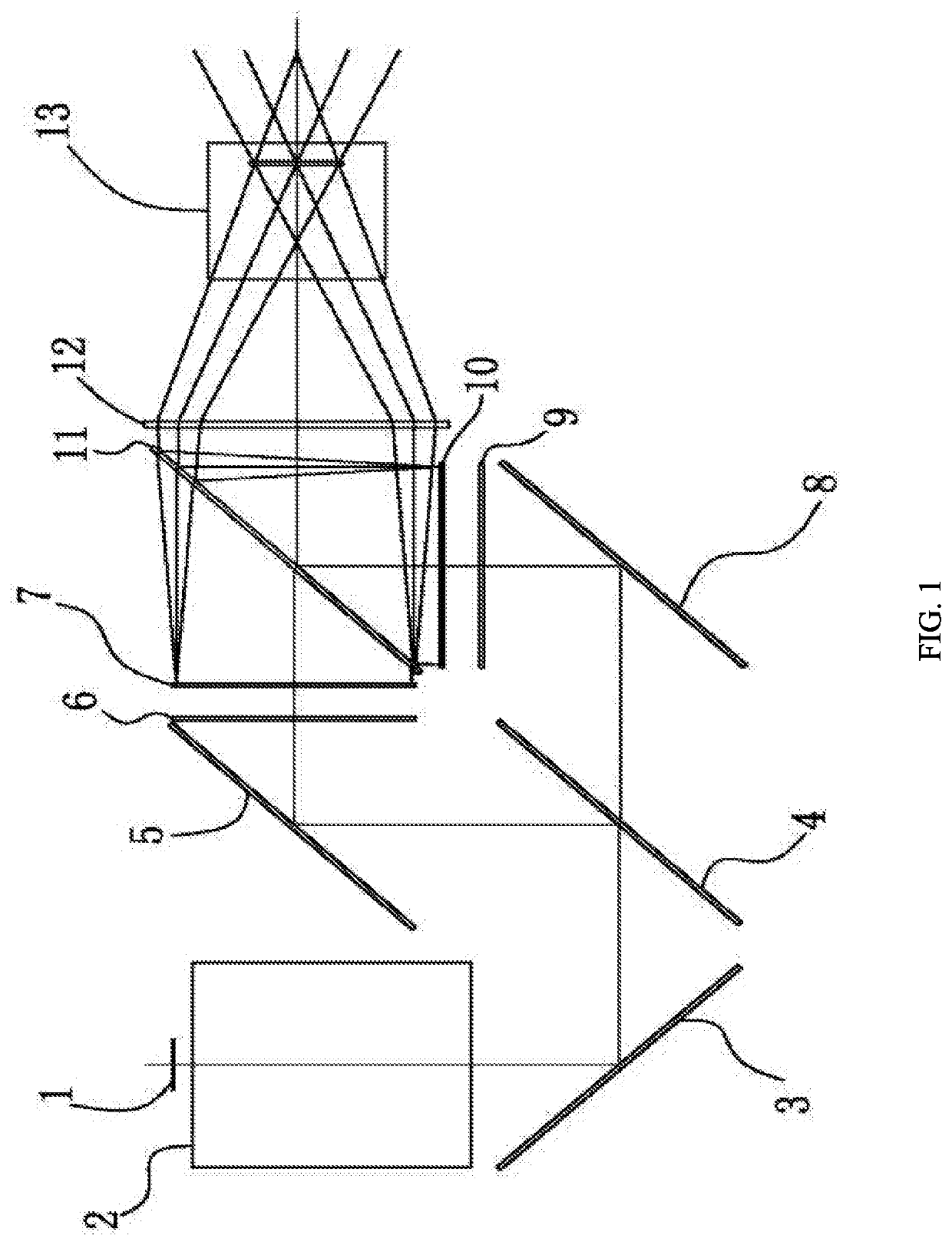
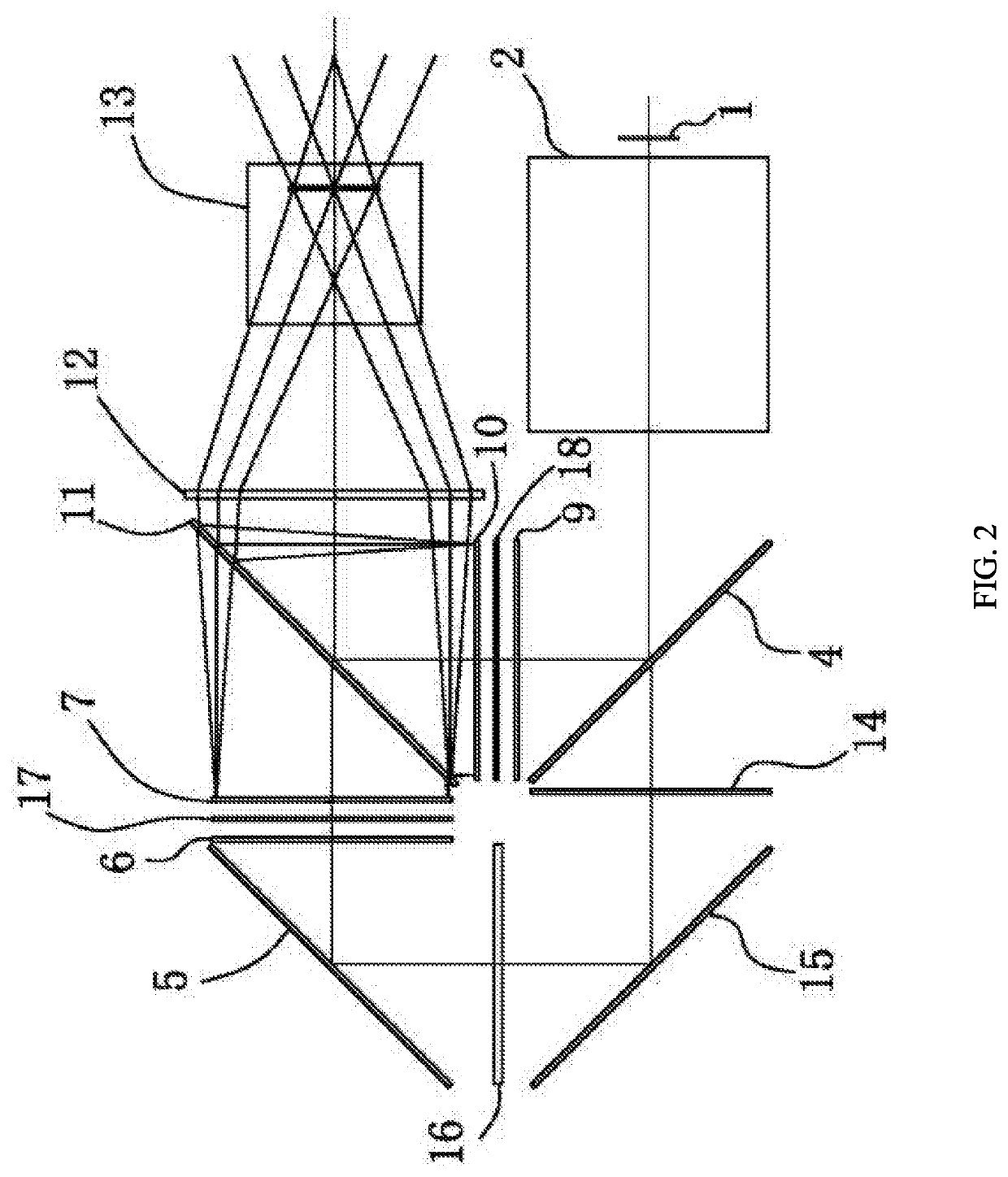
[0024]Referring to FIG. 1, FIG. 1 illustrates a principle structure of a two-piece LCD projector based on a PBS light splitting-converging manner according to the disclosure. The two-piece LCD projector shown in FIG. 1 includes an LED light source 1, a spotlighting device 2, a holophote 3, a first PBS device 4, a holophote 5, a focusing lens 6, a first LCD light valve module 7, a holophote 8, a focusing lens 9, a second LCD light valve module 10, a second PBS device 11, a field lens 12 and a projection lens 13.

[0025]The basic work principle of the two-piece LCD projector of the disclosure is that the light, emitted by the LED light source 1 is irradiated to the first PBS device 4 after passing through the spotlighting device 2 and the holophote 3, the first PBS device 4 divides an incident light into two paths of polarized lights namely P light and S light, one path is the S light which is irradiated ...


PUM

PropertyMeasurementUnit
sizeaaaaaaaaaa
sizeaaaaaaaaaa
sizeaaaaaaaaaa

Abstract

The disclosure provides a two-piece LCD projector based on a PBS (polarization beam splitter) light splitting-converging manner, including a first PBS device, a second PBS device, a first LCD light valve module and a second LCD light valve module, wherein a light emitted by an LED light source is divided into two paths of polarized lights namely P light and S light by the first PBS device after passing through a spotlighting device, one path is the S light which is irradiated to the first LCD light valve module, the other path is the P light which irradiated to the second LCD light valve module, the lights pass through two LCD light valve modules to be converged by the second PBS device, and the converged light passes through a field lens and a projection lens and finally reaches a screen, thereby achieving a projection function.

Description

CROSS-REFERENCE TO RELATED APPLICATIONS[0001]This application claims priority to Chinese Patent Application No. 201910494549.3 with a filing date of Jun. 6, 2019. The content of the aforementioned applications, including any intervening amendments thereto, are incorporated herein by reference.TECHNICAL FIELD[0002]The disclosure relates to a two-piece LCD projector.BACKGROUND OF THE PRESENT INVENTION[0003]For a long time, people habitually classify projectors based on, characteristics of a light valve, one of the most core devices of the projector in general, such as a DLP (digital light processing) projector, an LCD (liquid crystal display) projector, an LCOS (liquid crystal on silicon) projector, which are common at present.[0004]The common LCD projector all has two characteristics that the light valve adopts an LCD technology (for distinguishing DLP) and is of a transmission type (for distinguishing LCOS). The LCD projector generally has two principles and structure forms of a sig...

Claims


Application Information

Patent Timeline
Patent Type & Authority Applications(United States)
IPC IPC(8): H04N9/31G02F1/1335G02B27/26G03B21/14G02B30/25
CPCG02F2001/13355H04N9/3197G02F1/13362G03B21/14G02B30/25H04N9/3167H04N9/3105G03B21/2033G03B21/2073G03B21/2066G02F1/13355
Inventor GUO, HANWEN
Owner NAHHUA INTELLIGENT PRECISION MASCH SHENZHEN CO LTD
Learn More