
Microbubble generator and cooling water circulation system equipped with same

Inactive Publication Date: 2020-12-24
TOYOTA BOSHOKU KK
View PDF0 Cites 3 Cited by
  • Summary
  • Abstract
  • Description
  • Claims
  • Application Information

AI Technical Summary

Benefits of technology

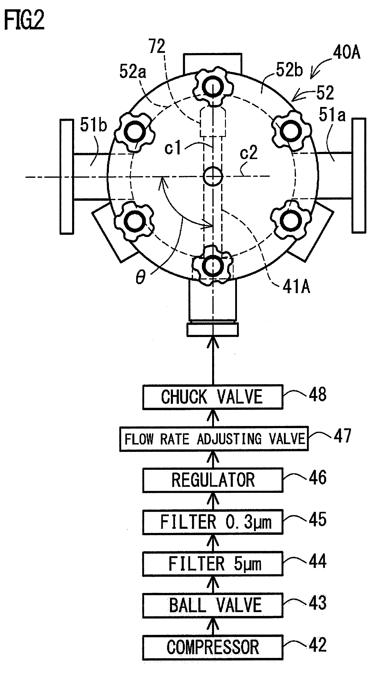
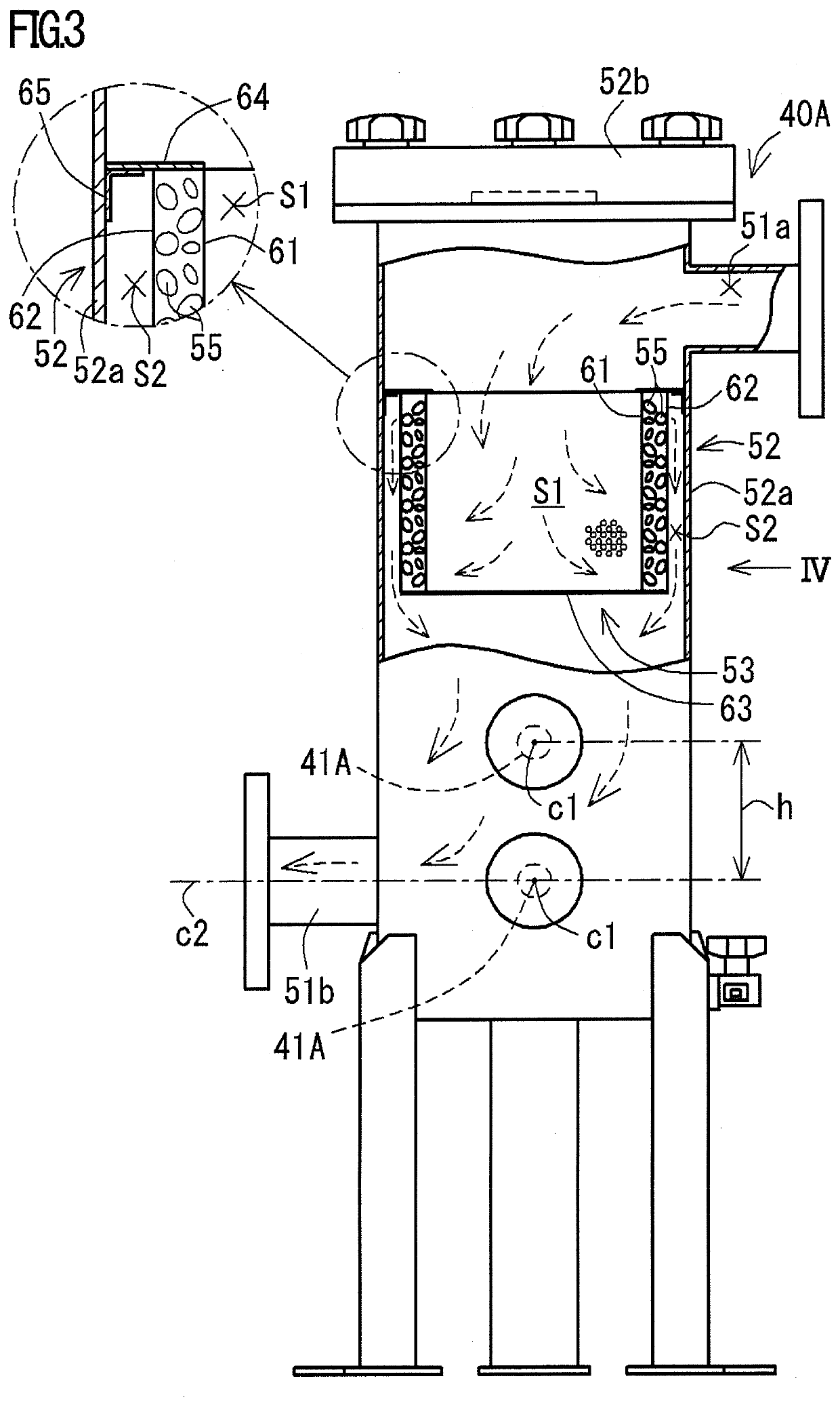
The present invention provides a microbubble generator that can produce ultrafine high concentration microbubbles in a liquid. The generator includes a straight pipe made of porous ceramics with one end connected to a compressor and the other end blocked, which allows gas pumped to the internal space of the straight pipe to pass through its pores and become microbubbles. The straight pipe has an average pore diameter of 1.5 μm or less. When the straight pipe has an outer diameter and an inner diameter that are different by 8 mm to 17 mm, microbubbles are more uniformly generated in the liquid. A filter is provided to remove oil components and prevent clogging of the pores of the straight pipe. When the straight pipe is disposed in a housing with an inflow and an outflow port, a liquid flowing through the housing can contain a large amount of microbubbles. The outflow port is provided in a side wall of the housing, and the straight pipe is disposed in the housing with a vertical distance of 200 mm or less between its axis and the outflow port, which allows a larger amount of microbubbles to be contained in the liquid.

Problems solved by technology

While a swirl flow type, a venturi type, an ejector type, and a pressurized dissolution type are known as conventional microbubble generators, there are some problems: first, bubbles or droplets cannot be sufficiently reduced in size.
Second, even though they can be sufficiently reduced in size, the amount generated is small.
Third, the generators above each have a complicated structure that requires much time and labor to manufacture it, and that is very expensive.

Method used


Image

  • Microbubble generator and cooling water circulation system equipped with same
  • Microbubble generator and cooling water circulation system equipped with same
  • Microbubble generator and cooling water circulation system equipped with same

Examples


example

[0065]Hereinafter, the present invention will be described in detail using an example with reference to the drawings.

[0066](1) Configuration of Cooling Water Circulation System

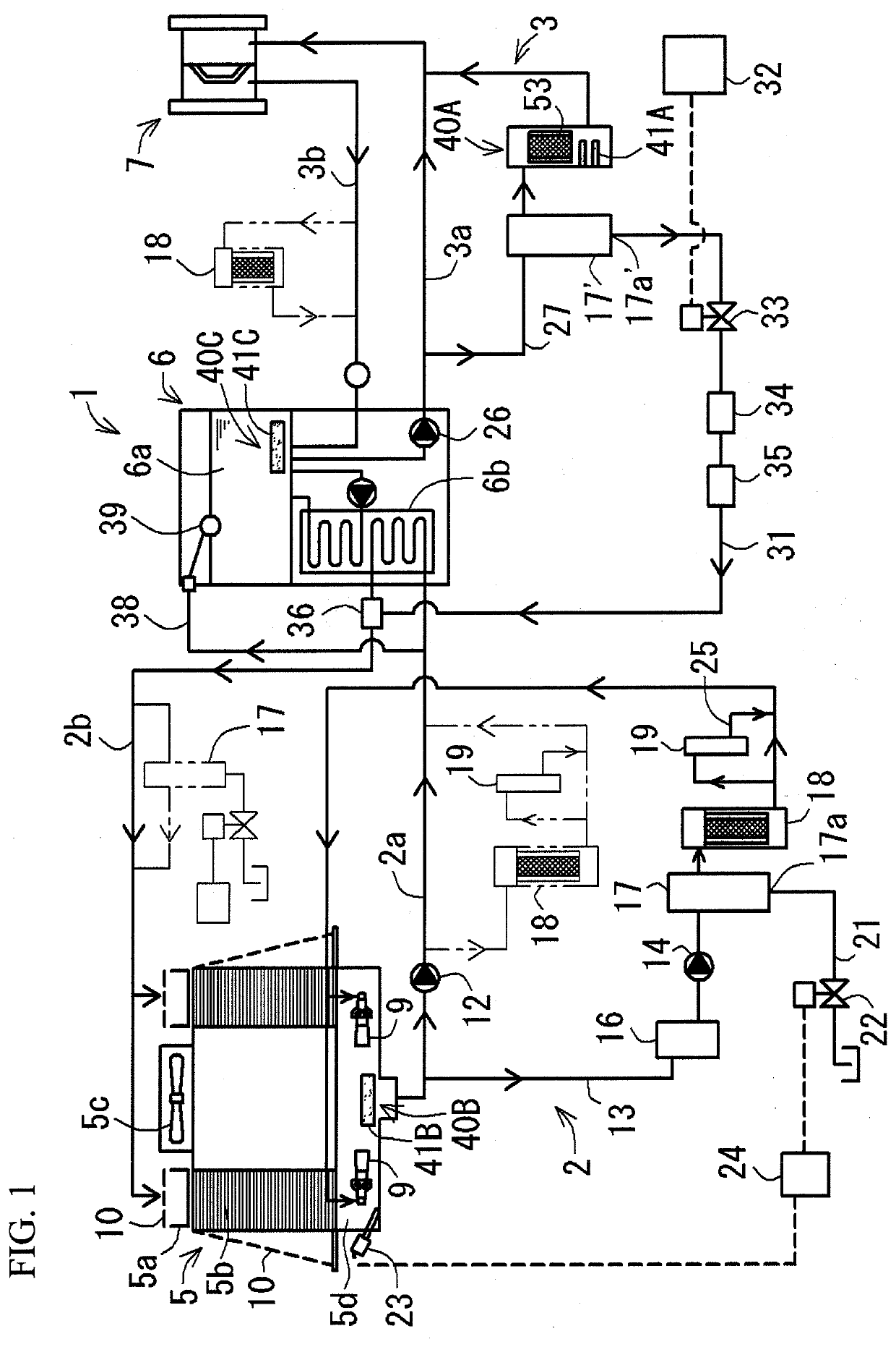
[0067]As illustrated in FIG. 1, a cooling water circulation system 1 according to the present example circulates cooling water in a circulation path, and includes microbubble generators 40A, 40B, and 40C described below. The circulation path includes a cooling-tower-side circulation path 2 for circulating the cooling water between a cooling tower 5 and a chiller machine 6, and a chiller-machine-side circulation path 3 for circulating the cooling water between a chiller machine 6 and a cooling target part 7. Examples of the cooling target part 7 include an injection molding device, a press working device, a welding device, a heating device, a trimming device, and the like.

[0068]The cooling tower 5 includes a water sprinkling tank 5a for storing and sprinkling cooling water increased in temperature fed from the ...


PUM

PropertyMeasurementUnit
Pore sizeaaaaaaaaaa
Diameteraaaaaaaaaa
Diameteraaaaaaaaaa

Abstract

The present microbubble generator is a microbubble generator for generating microbubbles in a liquid, including a straight pipe made of porous ceramics, having one end connected to a compressor and the other end blocked, and the straight pipe having an average pore diameter of 1.5 μm or less.

Description

TECHNICAL FIELD[0001]The present invention relates to a microbubble generator and a cooling water circulation system equipped with the same, and more particularly to a microbubble generator for generating microbubbles in liquid and a cooling water circulation system equipped with the same.BACKGROUND ART[0002]While a swirl flow type, a venturi type, an ejector type, and a pressurized dissolution type are known as conventional microbubble generators, there are some problems: first, bubbles or droplets cannot be sufficiently reduced in size. Second, even though they can be sufficiently reduced in size, the amount generated is small. Third, the generators above each have a complicated structure that requires much time and labor to manufacture it, and that is very expensive.[0003]Thus, various techniques have been proposed as a microbubble generator that solves the above problems (e.g., refer to Patent Literatures 1 and 2). Patent Literature 1 discloses an ultrafine bubble generator incl...

Claims


Application Information

Patent Timeline
IPC IPC(8): B01F3/04C02F3/20
CPCB01F2003/04361C02F3/202B01F3/04262B01F2003/04858B01F3/04248C02F1/50C02F5/02F28F25/06F28C1/04C02F2103/023C02F2303/22C02F2303/26C02F1/005C02F1/004C02F1/481C02F1/74B01F21/22B01F23/2323B01F25/313311B01F23/231231B01F23/2373B01F23/23123B01F23/23121
Inventor NAGATA, MASASUKE
Owner TOYOTA BOSHOKU KK
Learn More