Fueling system and method of fueling

Active Publication Date: 2020-12-24
VOLVO LASTVAGNAR AB
View PDF0 Cites 0 Cited by
  • Summary
  • Abstract
  • Description
  • Claims
  • Application Information

AI Technical Summary

Benefits of technology

The patent text describes a fueling system for vehicles that aims to safely and properly fill fuel tanks, prevent dangerous over-filling or nuisance under-filling, provide safety features, and prevent tank ruptures. The system includes a nozzle receptacle designed to prevent fuel leakage, an electric fill stop valve that minimizes wear and tear, and a vapor head space in the tank to allow for the liquid's thermal expansion. Additionally, the system offers advantages of facilitating proper nozzle connection and minimizing fuel dispenser wear and tear.

Problems solved by technology

This type of fill stop valve is subject to many failure modes.
In addition, when the fuel level is below the lower extension of the arm, the float arm may vibrate due to the motion of the truck.
This continuous vibration reduces the life expectancy of dynamic seals in the fill stop valves due to back-and-forth wear resulting in eventual leakages.
The wear on the seals also weakens the seals and those seals may rupture when the tanks are being filled under pressure.
Any leakage and / or rupture in the fill stop valve can allow fuel to continue to flow into the tank and over-fill it to an unsafe level.
Without sufficient vapor head space, high hydrostatic pressure of the expanding liquid due to increasing temperature could cause the metal tank to rupture, allowing the release of pressurized fuel and metal fragments.
The rapid discharge of flammable fuel to the immediate environment prevents tank ruptures, but can still pose a potential flammable condition to occur.
Filling multiple tanks on a vehicle from a common filling point (nozzle receptacle) increases the likelihood of overfilling and / or rapid discharge of fuel.
Failing to prevent over filling the tanks could lead to an uncontrolled fuel release.
In order to safely drain over filled tanks, other issues are presented such as additional equipment being required and safety risks associated with properly transferring fuel back to a supply tank.

Method used


Image

  • Fueling system and method of fueling
  • Fueling system and method of fueling
  • Fueling system and method of fueling

Examples


Embodiment Construction

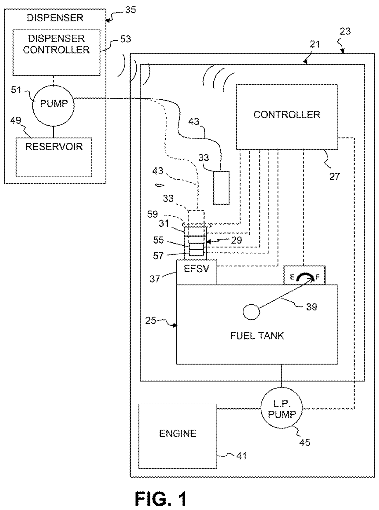
[0017]A fueling system 21 for an engine 41 of a vehicle 23 is shown in FIG. 1 and comprises a fuel tank 25 on the vehicle. The fueling system 21 further comprises a controller 27 (such as an engine control unit (ECU) or a dedicated Fuel Control Unit (FCU)), which can be remote from the vehicle but in the illustrated embodiment is shown as part of the vehicle. The inventive fueling system 21 is particularly adapted for use with a pressurized fuel system, however, the invention also has applicability to unpressurized fuel systems.

[0018]The fueling system 21 further comprises a fuel nozzle receptacle 29 connected to the fuel tank 25, the fuel nozzle receptacle including a receptacle sensor 31 configured to send a signal to the controller 27 indicative of whether a fuel nozzle 33 of a fuel dispenser 35 is received in the fuel nozzle receptacle. The receptacle sensor 31 can be in the form of a switch that is closed (or opened) when the fuel nozzle 33 (shown in phantom in FIG. 1) is prope...


PUM


Abstract

A fueling system for an engine includes a fuel tank, a controller, a fuel nozzle receptacle connected to the fuel tank, the fuel nozzle receptacle including a receptacle sensor configured to send a signal to the contoller indicative of whether a fuel nozzle of a fuel dispenser is received in the fuel nozzle receptacle, and an electric fill slop valve between the fuel tank and the fuel nozzle receptacle, the electric fill stop valve being, configured to be controlled to open and close in response to a signal from the controller. The controller can be configured to receive at least one of (a) a signal whether a fuel nozzle of a fuel dispenser is received in a fuel nozzle receptacle connected to the fuel tank, and (b) a signal whether a fuel level of the fuel tank is full, and to control the electric fill stop valve to close when a signal is sent to the controller that at least one of (a) the fuel nozzle is not received in the fuel nozzle receptacle when the controller is configured to receive the signal whether the fuel nozzle of a fuel dispenser is received in the fuel nozzle receptacle, and (b) the fuel level of the fuel tank is full when the controller is configured to receive the signal whether the fuel level of the fuel tank is full.

Description

BACKGROUND AND SUMMARY[0001]The present invention relates to a fueling system and a method of fueling, particularly suited for engines, more particularly for engines of vehicles, and still more particularly suited for pressurized fueling systems.[0002]There is substantial interest in ground transportation vehicles using low vapor pressure fuel in a liquid phase. Low vapor pressure fuel is normally a gas at atmospheric pressure, but will become a liquid when subjected to a pressure above atmospheric. Such fuel may be any low vapor pressure fuel, such as, for example, Propane or Dimethyl Ether (DME).[0003]It is important to be able to fill fuel tank(s) on vehicles to a safe and proper fuel level, and it is important to prevent dangerous over-filling or nuisance under-filling of the tanks. Nuisance under-filling may occur in multiple tanks arrangements when a dispenser senses a backpressure in the fuel line and shuts off because a first tank has filled before another tank. It is also d...

Claims


Application Information

Patent Timeline
IPC IPC(8): B60K15/03B60K15/04
CPCB60K15/04B60K2015/0323B60K2015/03302B60K15/03006B60K2015/0319B60K2015/03019B60K2015/03217B60K2015/0458B60K2015/03131B60K2015/03203B60K15/03B60K2015/049F02M25/089F02M37/0076F02M37/0088F02M37/20
Inventor HOOVER, DALELASSESSON, BENGT
Owner VOLVO LASTVAGNAR AB
Why Eureka
Try Eureka