Substrate integrated waveguide antenna

a waveguide antenna and integrated technology, applied in the direction of resonant antennas, individually energised antenna arrays, polarised antenna unit combinations, etc., can solve the problem of relatively large footprint of antenna arrays in electronic devices wherein they are used, and achieve the effect of reducing the footprint of antenna arrays and being easy to integra

Active Publication Date: 2020-12-24
SONY CORP
View PDF0 Cites 6 Cited by
  • Summary
  • Abstract
  • Description
  • Claims
  • Application Information

AI Technical Summary

Benefits of technology

[0032]The present design may provide a compact structure since every SIW-antenna is configured to radiate both vertically and horizontally polarized electromagnetic radiation. Hence, the present design may allow for reducing the footprint of the antenna array as compared for example with an array antenna as illustrated in FIG. 1.
[0033]The preset design may further give freedom to where to place the antenna array. The antenna array may form part of a circuit board. The antenna array may be placed at an edge of a circuit board. Hence, the present antenna may be easily integrated in for example a mobile device. The present antenna may, e.g., form part of a circuit design of the mobile device.

Problems solved by technology

However, such an array antenna leaves a relatively large footprint in the electronic device wherein it is used.

Method used


Image

  • Substrate integrated waveguide antenna
  • Substrate integrated waveguide antenna
  • Substrate integrated waveguide antenna

Examples


Embodiment Construction

[0045]The present invention will now be described more fully hereinafter with reference to the accompanying drawings, in which currently preferred embodiments of the invention are shown. This invention may, however, be embodied in many different forms and should not be construed as limited to the embodiments set forth herein; rather, these embodiments are provided for thoroughness and completeness, and to fully convey the scope of the invention to the skilled person.

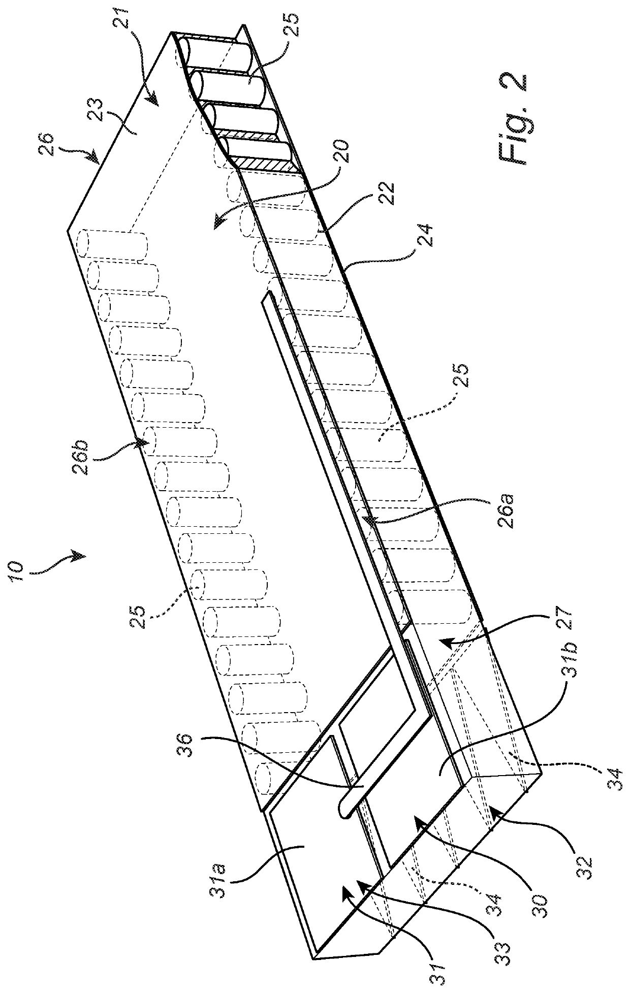
[0046]FIG. 2 illustrates a Substrate Integrated Waveguide, SIW, antenna 10 according to the present invention. In the literature the SIW antenna may also be referred to as a post-wall waveguide or a laminated waveguide. The SIW antenna 10 according to the present invention comprises a SIW structure 20 and a parallel plate resonator 30.

[0047]The SIW structure 20 is a rectangular guide 21 for electromagnetic waves. The guide 21 is formed within a substrate 22. The substrate 22 is made of a dielectric material. The substrat...


PUM


Abstract

A SIW-antenna (10) is disclosed. The SIW-antenna comprises a SIW-structure (20) extending along a horizontal plane for guiding electromagnetic waves along a longitudinal direction from a first feed (26) to a radiation aperture (27), and a parallel plate resonator (30) arranged at the radiation aperture (27), the parallel plate resonator (30) comprising a first flat portion (31) extending in a first plane parallel with the horizontal plane and a second flat portion (32) extending in a second plane parallel with the horizontal plane, wherein the first and second planes are separate from each other. The first flat portion (31) comprises an additional antenna structure (33) being connected to a second feed (36). The second flat portion (32) comprises a plurality of flat tabs (34) extending in the longitudinal direction. The SIW-structure (20) is configured to radiate electromagnetic waves polarized in a first direction. The additional antenna structure (33) is configured to radiate electromagnetic waves polarized in a second direction. The second direction is orthogonal to the first direction. Also an antenna array (200) comprising a plurality of SPAT antennas (10) as well as an electronic device comprising such an antenna array are disclosed.

Description

TECHNICAL FIELD[0001]The present invention relates to a substrate integrated waveguide antenna. The present invention further relates to an array antenna comprising a plurality of substrate integrated waveguide antennas.BACKGROUND[0002]In mobile industry today higher frequency bands such as the mm wave band, 10 GHz up to about 100 GHz, is heavily investigated due to the potential bandwidth available. In order to achieve good performance in the mm wave band an array antenna comprising multiple antennas arranged in an array antenna will most probably be needed. This both in order to achieve antenna diversity and in order to get an antenna that may emit electromagnetic waves having dual polarization. Antenna diversity may be achieved because multiple antennas offer a receiver several observations of the same signal. Further, dual polarization antennas may be used for multiplexing wherein two channels of information may be transmitted on the same carrier frequency by using waves of two ...

Claims


Application Information

Patent Timeline
Patent Type & Authority Applications(United States)
IPC IPC(8): H01Q21/24H01Q1/22H01Q9/04
CPCH01Q9/0407H01Q21/24H01Q1/2283H01Q9/065H01Q9/40H01Q13/06H01Q21/08H01Q25/001
Inventor YING, ZHINONGZHAO, KUN
Owner SONY CORP
Why Eureka
Try Eureka