Method for producing at least one high-frequency contact element or a high-frequency contact element arrangement and associated apparatuses

Pending Publication Date: 2020-12-24
ROSENBERGER HOCHFREQUENZTECHNIK GMBH & CO KG
View PDF0 Cites 0 Cited by
  • Summary
  • Abstract
  • Description
  • Claims
  • Application Information

AI Technical Summary

Benefits of technology

[0019]Against this background, the present invention is based on the object of developing a method for inexpensive production of a contact element for contact-making and transmission of a high-frequency signal, which is optimized in terms of its electrical and mechanical properties and can also be produced with very small d

Problems solved by technology

The mentioned electrical and mechanical requirements placed on the contact elements necessarily result in very complicated geometries, in very small dimensions and in material combinations which, disadvantageously, cannot be produced using conventional manufacturing technologies.
The miniaturization of contact elements is also subject to a technical limit using such conventional manufacturing tech

Method used


Image

  • Method for producing at least one high-frequency contact element or a high-frequency contact element arrangement and associated apparatuses
  • Method for producing at least one high-frequency contact element or a high-frequency contact element arrangement and associated apparatuses
  • Method for producing at least one high-frequency contact element or a high-frequency contact element arrangement and associated apparatuses

Examples


Embodiment Construction

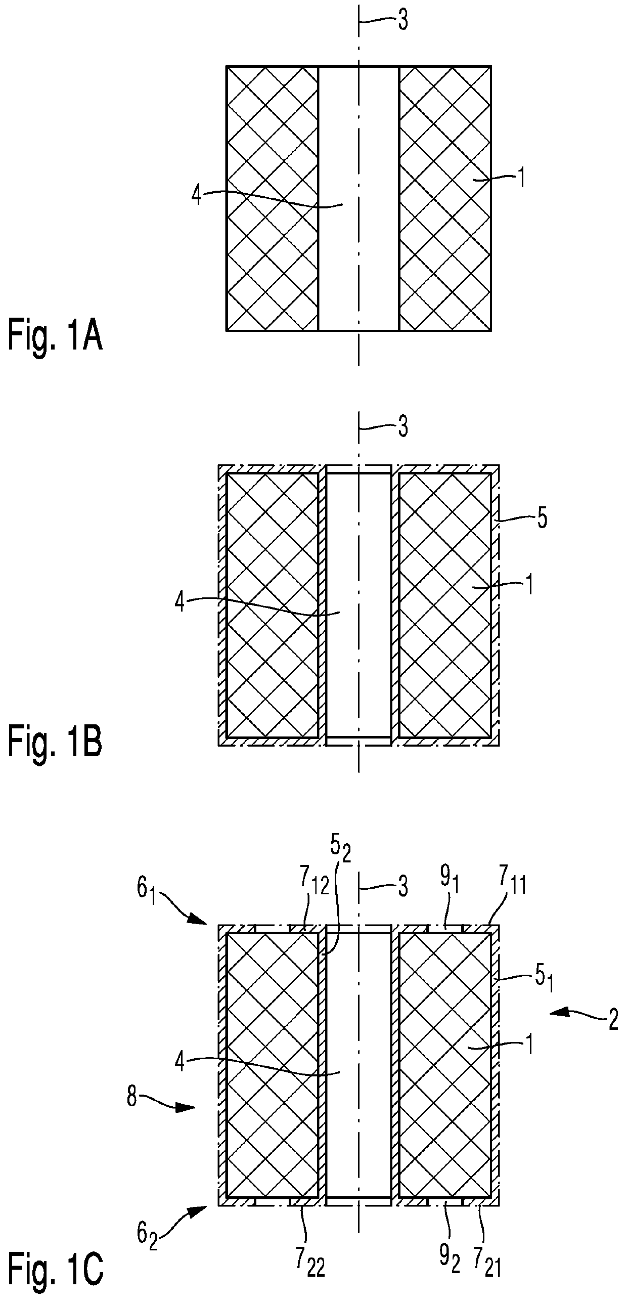
[0112]In the text which follows, the principle of the method according to the invention for producing a high-frequency contact element will be explained with reference to FIGS. 1A to 1C:

[0113]In a first manufacturing step shown in FIG. 1A, a basic body part 1 of the high-frequency contact element 2 according to the invention is produced from a dielectric material. The basic body part 1 has a bushing 4 in the direction of its longitudinal axis 3.

[0114]In the cross-sectional illustrations shown in FIGS. 1A to 1C, the basic body part 1 has a single bushing 4, which runs along the longitudinal axis 3. The geometry of the dielectric basic body part 1 does not necessarily need to be hollow-cylindrical, as is illustrated in FIGS. 1A to 1C for reasons of simplicity.

[0115]Preferably, the geometry of the basic body part 1 is formed so as to be rotationally symmetrical with respect to the longitudinal axis 3 in order to realize concentricity between the inner conductor coating and the outer co...


PUM


Abstract

The present invention relates to a method for producing at least one high-frequency contact element or a high-frequency contact element arrangement comprising at least one such high-frequency contact element. The method includes producing a basic body part of each high-frequency contact element from a dielectric material by means of an additive manufacturing method, wherein the basic body part has a bushing between a first end and a second end of a longitudinal extent of the basic body part. In addition, the method includes coating the dielectric basic body part with an electrically conductive layer and removing the electrically conductive layer in a region surrounding the bushing at the first end and at the second end of the basic body part so as to form an electrically conductive coating on the outer conductor side and an electrically conductive coating on the inner conductor side. The present invention also relates to a high-frequency contact element or a high-frequency contact element arrangement.

Description

FIELD OF THE INVENTION[0001]The present invention relates to a method for producing at least one high-frequency contact element or a high-frequency contact element arrangement and associated apparatuses.TECHNICAL BACKGROUND[0002]Modern connection technology comprises not only contact elements for contact-making and transmission of DC voltage signals or low-frequency signals in accordance with DE 10 2016 004 520 A1, but also contact elements for contact-making and transmission of high-frequency signals. Here and in the text which follows, a high-frequency signal is understood to mean a signal having a frequency of above 3 MHz to 30 THz, i.e. virtually the entire range of the electromagnetic spectrum.[0003]Contact elements are preferably used for transmitting high-frequency signals between contact terminals of two adjacent printed circuit boards (so-called board-to-board connection).[0004]A further large application area of contact elements for high-frequency signals is the contact-ma...

Claims


Application Information

Patent Timeline
IPC IPC(8): H01R43/00H01R43/16H01R13/24
CPCH01R24/50H01R43/16H01R13/035H01R2201/20H01R13/2414H01R12/714H01R43/007H01R12/7076H01R12/73H01R13/2421H01R13/2442H01R13/2485H01R13/2492H01R13/6476
Inventor SCHÜTT, HAUKESCHMIDT, WALDEMARHENNIGER-LUDWIG, ALEXANDRA
Owner ROSENBERGER HOCHFREQUENZTECHNIK GMBH & CO KG
Why Eureka
Try Eureka