Stator, method of manufacturing stator, and outer rotor type motor

a stator and rotor body technology, applied in the direction of stator/rotor body manufacturing, magnetic circuit rotating parts, magnetic circuit shape/form/construction, etc., can solve the problems of reducing the space factor of the coil, difficulty in winding bold wires, and inability to perform automatic winding, so as to maintain roundness, improve productivity, and high space factor

Active Publication Date: 2020-12-24
SHINANO KENSHI
View PDF0 Cites 1 Cited by
  • Summary
  • Abstract
  • Description
  • Claims
  • Application Information

AI Technical Summary

Benefits of technology

[0024]It is possible to provide a stator in which automatic winding can be performed with the high space factor by the winding machine with respect to the stator core with narrow gaps between teeth edges of pole teeth and the segment cores are assembled in the annular shape while maintaining roundness, and the method of manufacturing the stator with improved productivity. It is also possible to provide an outer rotor type motor with the high space factor and improved productivity by using the above stator.

Problems solved by technology

For example, in a structure in which many slots are provided in a stator core of an outer rotor type motor, gaps between teeth edges of pole teeth provided to extend on an outer side in a radial direction from annular core members are narrow, which makes it difficult to wind bold wire as a coil, and when a nozzle of a winding machine is not capable of entering, it is impossible to perform automatic winding.
Furthermore, a space for the nozzle of the winding machine entering between teeth edges of the pole teeth is necessary, so that a space factor of the coil is reduced and winding the coil at high density is difficult, and therefore, manual winding work has to be selected.

Method used


Image

  • Stator, method of manufacturing stator, and outer rotor type motor
  • Stator, method of manufacturing stator, and outer rotor type motor
  • Stator, method of manufacturing stator, and outer rotor type motor

Examples


Embodiment Construction

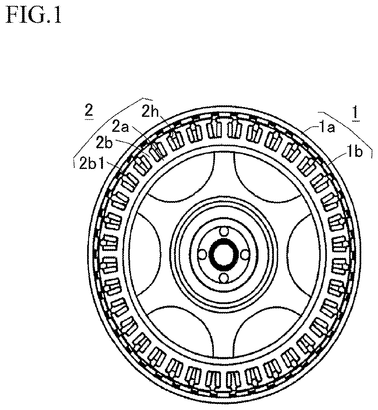
[0037]Hereinafter, a stator, a method of manufacturing the stator, and an outer rotor type motor according to the present invention will be explained with reference to the attached drawings. First, an outline structure of the outer rotor type motor will be explained with reference to FIG. 1. A DC brushless motor is used as the outer rotor type motor in the embodiment.

[0038]As shown in FIG. 1, an outer rotor type motor including a rotor 1 and a stator 2 is used for the DC brushless motor. The rotor 1 is configured so that annular rotor magnets 1b in which N-poles and S-poles are alternately magnetized in a circumferential direction are supported on an inner peripheral surface of an annular back yoke 1a (a magnetic material such as iron and SUS) connected to a rotor shaft. The rotor magnets 1b are arranged so as to face pole teeth 2b of a stator core 2c.

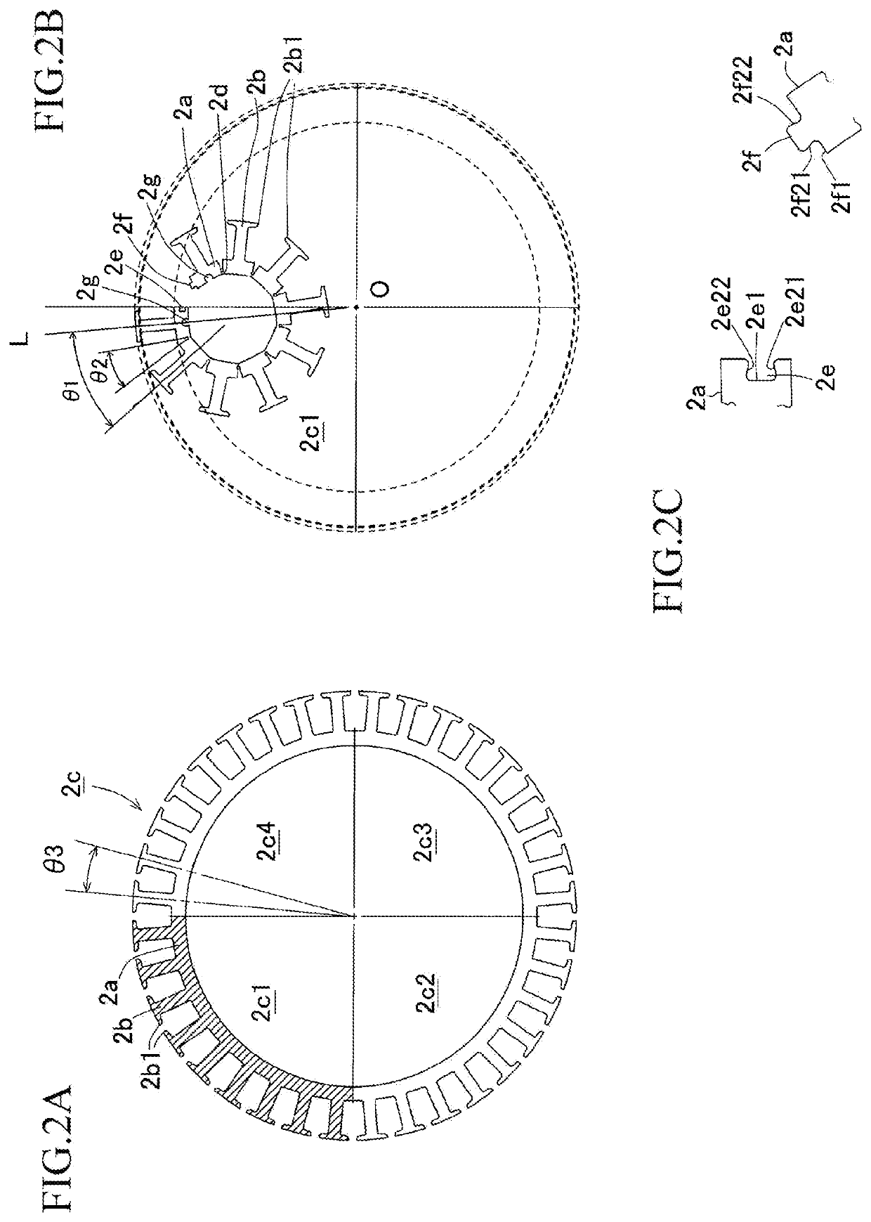
[0039]The stator 2 adopts the stator core 2c in which the pole teeth 2b are provided to protrude on annular yoke parts 2a so as to f...


PUM


Abstract

Groove holes capable of positioning each of the segment cores with respect to a winding jig in an arc attitude with wide gaps between the teeth edges of respective pole teeth are respectively formed in yoke parts positioned at both end parts of each of the segment cores in a longitudinal direction.

Description

CROSS-REFERENCE TO RELATED APPLICATION[0001]This application is based upon and claims the benefit of priority of the prior Japanese Patent Application No. 2019-116160, filed on Jun. 24, 2019, and the entire contents of which are incorporated herein by reference.TECHNICAL FIELD[0002]The present invention relates to a stator, a method of manufacturing the stator, and an outer rotor type motor.BACKGROUND ART[0003]For example, in a structure in which many slots are provided in a stator core of an outer rotor type motor, gaps between teeth edges of pole teeth provided to extend on an outer side in a radial direction from annular core members are narrow, which makes it difficult to wind bold wire as a coil, and when a nozzle of a winding machine is not capable of entering, it is impossible to perform automatic winding. Furthermore, a space for the nozzle of the winding machine entering between teeth edges of the pole teeth is necessary, so that a space factor of the coil is reduced and wi...

Claims


Application Information

Patent Timeline
Patent Type & Authority Applications(United States)
IPC IPC(8): H02K1/14H02K1/27H02K15/02H02K21/22
CPCH02K15/022H02K1/146H02K21/22H02K1/2786H02K1/148H02K15/095H02K1/2791
Inventor HIGASHIYAMA, KEITAHOSHINO, MASAYOSHI
Owner SHINANO KENSHI
Why Eureka
Try Eureka