Electromagnetic impedance spectroscopy apparatus and related planar sensor system

a technology planar sensor, which is applied in the field of electromagnetic impedance spectroscopy, can solve the problems of increasing noise level and inhibiting accurate determination of measured impedance, and achieves the effects of less strength, minimal modification, and greater strength

Active Publication Date: 2020-12-31
TRANSTECH SYST
View PDF0 Cites 5 Cited by
  • Summary
  • Abstract
  • Description
  • Claims
  • Application Information

AI Technical Summary

Benefits of technology

[0006]The objective of the enclosed capacitive volumes is to isolate and control the effects of the field lines which emanate from both the transmitting electrode and the receiving electrode and go to the backer ground plate, and the field lines that pass through the soil and go to the backer ground plate. One group of field lines are proximate the transmitting electrode, transverse the soil at a shallow depth and interact with the backer ground plate in the region of the transmitting electrode. These field lines have greater strength (relative to other lines described herein) and are minimally modified by their route through the soil. Field lines will also penetrate deeply into the subsurface of the soil and interact with the backer ground plate in the region proximate the receiving electrode, as well as with the receiving electrode itself. These field lines will have less strength and are more affected (e.g., modified) by their route through the soil. In the sensor system of U.S. Pat. No. 7,219,024, the interaction of all of these field lines creates a varying field in the volume created by the electrodes and the intermediate ground. This varying field produces an uncontrolled parasitic capacitance that increases the noise level relative to the received signal, which inhibits accurate determination of the measured impedance. The creation of enclosed and separate capacitive volumes, the geometry and volumes of which can be designed to control the degree of the parasitic capacitance, can significantly reduce this problem.

Problems solved by technology

This varying field produces an uncontrolled parasitic capacitance that increases the noise level relative to the received signal, which inhibits accurate determination of the measured impedance.

Method used


Image

  • Electromagnetic impedance spectroscopy apparatus and related planar sensor system
  • Electromagnetic impedance spectroscopy apparatus and related planar sensor system
  • Electromagnetic impedance spectroscopy apparatus and related planar sensor system

Examples


Embodiment Construction

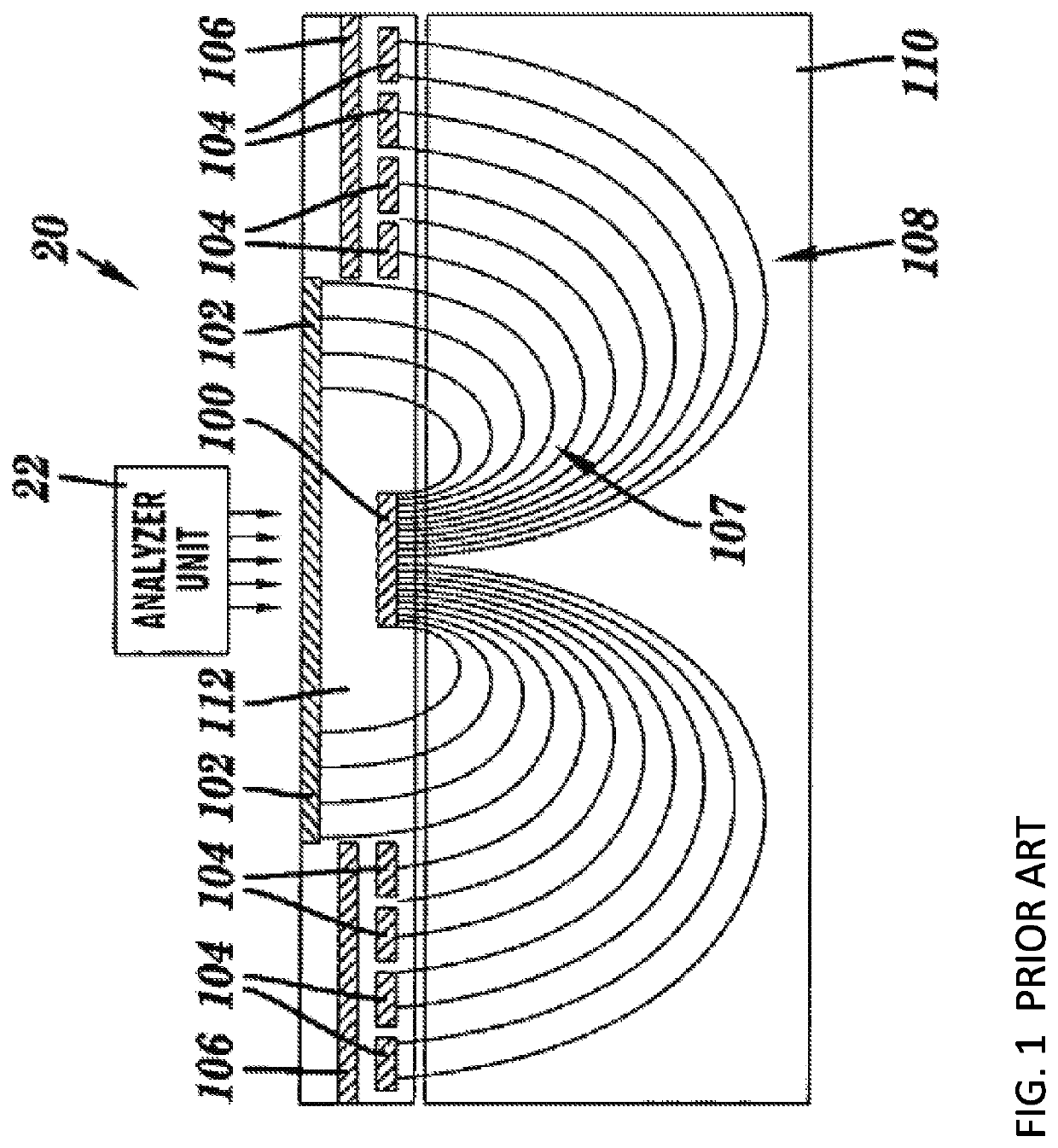
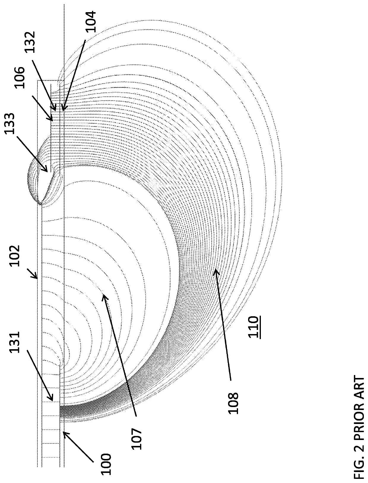
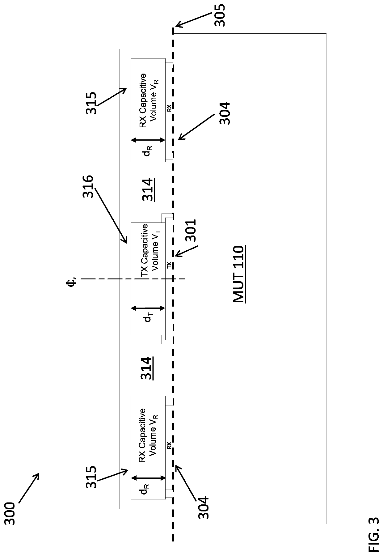
[0074]As described herein, various aspects of the disclosure include systems for characterizing a material under test (MUT). In particular, sensor systems disclosed according to various embodiments include a backer ground plate which enclose the electrodes to create volumes for controlling the parasitic impedance that can cause signal interference in characterization of a MUT.

[0075]According to various embodiments, an MUT can include any material capable of being characterized via one or more approaches shown and / or described herein. In various embodiments, an MUT includes an inorganic material such as a soil, an organic material such as grain, or a biological material such as tissue, sub-tissue, organs, fluids, etc. An MUT can include synthetic, composite and / or other blended / modified materials. An MUT can also include elemental materials, as well as materials including impurities. It is understood that the teachings described according to the various embodiments herein can be appl...


PUM

PropertyMeasurementUnit
depthaaaaaaaaaa
depthaaaaaaaaaa
depthaaaaaaaaaa

Abstract

According to various implementations, an apparatus for electromagnetic impedance spectra graphic characterization of a material under test (MUT) includes: a planar array of at least two electrodes configured to be placed in electromagnetic communication with the MUT, wherein during operation of the planar array, at least one of the electrodes comprises a transmitting electrode for transmitting an electromagnetic signal over a range of frequencies through the MUT to at least one receiving electrode in the planar array; and a backer ground plate at least partially surrounding the at least two electrodes, the backer ground plate being electrically grounded and insulated from the at least two electrodes, wherein the backer ground plate extends from a plane formed by the at least two electrodes and separates the at least two electrodes to create an electrically isolated volume proximate to the at least two electrodes.

Description

CROSS-REFERENCE TO RELATED APPLICATION[0001]This application claims priority to U.S. Provisional Patent Application No. 62 / 619,275, filed on Jan. 19, 2018, which is hereby incorporated by reference in its entirety.TECHNICAL FIELD[0002]Aspects of the disclosure relate to electromagnetic impedance spectroscopy. In particular, aspects of the disclosure relate to an apparatus and related planar sensor system for use in characterizing selected portions of a material under test.BACKGROUND[0003]In U.S. Pat. No. 7,219,024 (which is hereby incorporated by reference in its entirety), a system is described for conducting electromagnetic impedance spectroscopy to non-invasively determine the in-place density (i.e., compaction) and moisture of various engineering materials with specific interest in soils. A fundamental component of this conventional system is the sensor system. Current testing standards for in-place soil testing, such as ASTM standard D1556 (for sand cone method), ASTM standard ...

Claims


Application Information

Patent Timeline
Patent Type & Authority Applications(United States)
IPC IPC(8): G01N27/02G01N27/22
CPCG01N27/226G01N27/026
Inventor GEIER, MANFREDBLOT, ADAM D.WESTCOTT, ANDREW J.
Owner TRANSTECH SYST
Why Eureka
Try Eureka