
Field installable fiber optic connector

a fiber optic connector and installation technology, applied in the field of field installationable fiber optic connectors and systems, can solve problems such as information loss, and achieve the effect of reducing field installation tim

Active Publication Date: 2020-12-31
SENKO ADVANCED COMPONENTS
View PDF0 Cites 1 Cited by
  • Summary
  • Abstract
  • Description
  • Claims
  • Application Information

AI Technical Summary

Benefits of technology

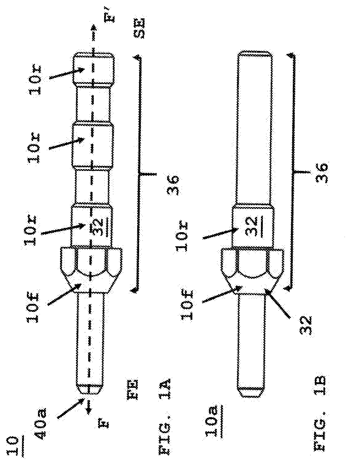
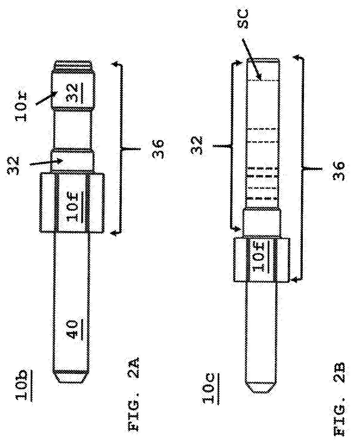
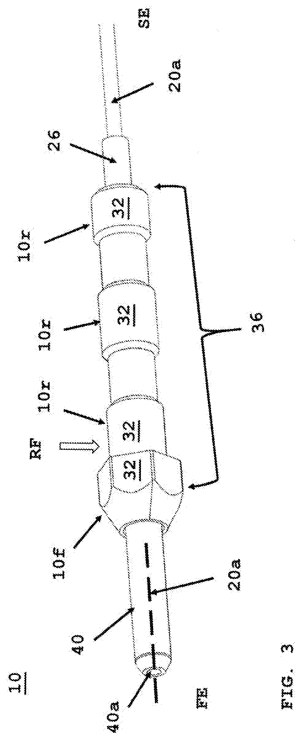
The present invention reduces the time it takes to install an optical fiber in a ferrule flange assembly by creating crimp zones along the ferrule flange assembly and the ferrule assembly main body. A protective tubing is used to further protect the optical fiber from breakage or cracking. The pull strength of the optical cable should be greater than 400 Newtons. The crimp zones secure the optical fiber and improve stability and alignment with the opposing fiber optic connector endface. The optical fiber in the ferrule flange assembly is protected from excess pulling or stress.

Problems solved by technology

Any cracks cause the light signal to become distorted which leads to information loss.

Method used


Image

  • Field installable fiber optic connector
  • Field installable fiber optic connector
  • Field installable fiber optic connector

Examples


Embodiment Construction

[0038]The following terms shall have, for the purposes of this application, the respective meanings set forth below.

[0039]A connector is a device that completes a communication path from a fiber strand transmits a light signal to another connector or to transceiver electronics. The electronics convert the light signal into a digital signal. A connector is inserted and secured at either end of adapter, for example, a ferrule connector (FC), a fiber distributed data interface (FDDI) connector, an LC connector, a mechanical transfer (MT) connector, a standard connector (SC) connector, an SC duplex connector, or a straight tip (ST) connector. The connector may generally be defined by a connector housing body, an external latch or recess to secure said connector into adapter opening and one or more ferrules having optic fibers therein. In some embodiments, the housing body may incorporate any or all of the components described herein.

[0040]A receptacle is an adapter with internal structu...


PUM

PropertyMeasurementUnit
radial forceaaaaaaaaaa
strengthaaaaaaaaaa
diameteraaaaaaaaaa

Abstract

A field installable fiber optic connector is formed without the need to splice two opposing optical fibers together. A ferrule flange assembly with one or more crimp zones secures an optical fiber therein. The assembly is secured within a plug frame housing that has a bias spring, both secured therein by an extender cap. A cable retainer with at least two wings secures the optical cable when a retainer nut is screwed onto a backpost of the extender cap.

Description

CROSS REFERENCE TO RELATED APPLICATIONS[0001]This application claims priority to U.S. Provisional Patent application No. 62 / 866,958 filed Jun. 26, 2019 and U.S. Provisional Patent Application No. 62 / 971,350 filed Feb. 7, 2020 and both patent applications are fully incorporated by reference.FIELD OF THE INVENTION[0002]The present disclosure relates generally to field installable fiber optic connectors and systems, and more specifically connecting a fiber optic cable to a fiber optic connector with an optical fiber in the field using a ferrule assembly with one or more crimp zones, and further securing the fiber optic cable components with different fiber optic connector components to form a fiber optic connector assembly.BACKGROUND[0003]The prevalence of the Internet has led to unprecedented growth in communication networks. Consumer demand for service and increased competition has caused network providers to continuously find ways to improve quality of service while reducing cost.[0...

Claims


Application Information

Patent Timeline
Patent Type & Authority Applications(United States)
IPC IPC(8): G02B6/38
CPCG02B6/3887G02B6/3869G02B6/3857G02B6/406G02B6/3888
Inventor IIZUMI, KENJITAKANO, KAZUYOSHI
Owner SENKO ADVANCED COMPONENTS
Learn More