Electrolytic capacitor

a technology of electrolytic capacitors and capacitors, applied in capacitors, capacitor terminals, capacitors, etc., can solve the problems of reducing the volume of sealing members, reducing the reliability of sealing members, and easy exposure of rubber sealing members to the opening of packaging cases, so as to prevent oxidation degradation of sealing members, enhance adhesion, and high reliability over a long period of time

Active Publication Date: 2020-12-31
PANASONIC INTELLECTUAL PROPERTY MANAGEMENT CO LTD
View PDF0 Cites 1 Cited by
  • Summary
  • Abstract
  • Description
  • Claims
  • Application Information

AI Technical Summary

Benefits of technology

[0014]With the electrolytic capacitor according to an aspect of the present invention, it is possible to realize high reliability over a long period of time even under severe operating conditions, by filling a resin member between a sealing member ...

Problems solved by technology

However, although the adhesive described in PTL 1 is injected from the recess of the non-depressed portion located around the depressed portion of the base plate, and assists the fixing of the capacitor body to the base plate, the rubber sealing member attached to the opening of the packaging case is easily exposed, during use, to air (oxygen) and/or water (moisture) entering the packaging case via holes provided in the base plate and is very susceptible to oxidation.
When oxidized, the sealing member undergoes a reduction in volume and becomes susceptible to cracking, and the molecular weight of the rubber that forms the sealing member is reduced, and the carbon molecules contained in th...

Method used


Image

  • Electrolytic capacitor
  • Electrolytic capacitor
  • Electrolytic capacitor

Examples


first embodiment

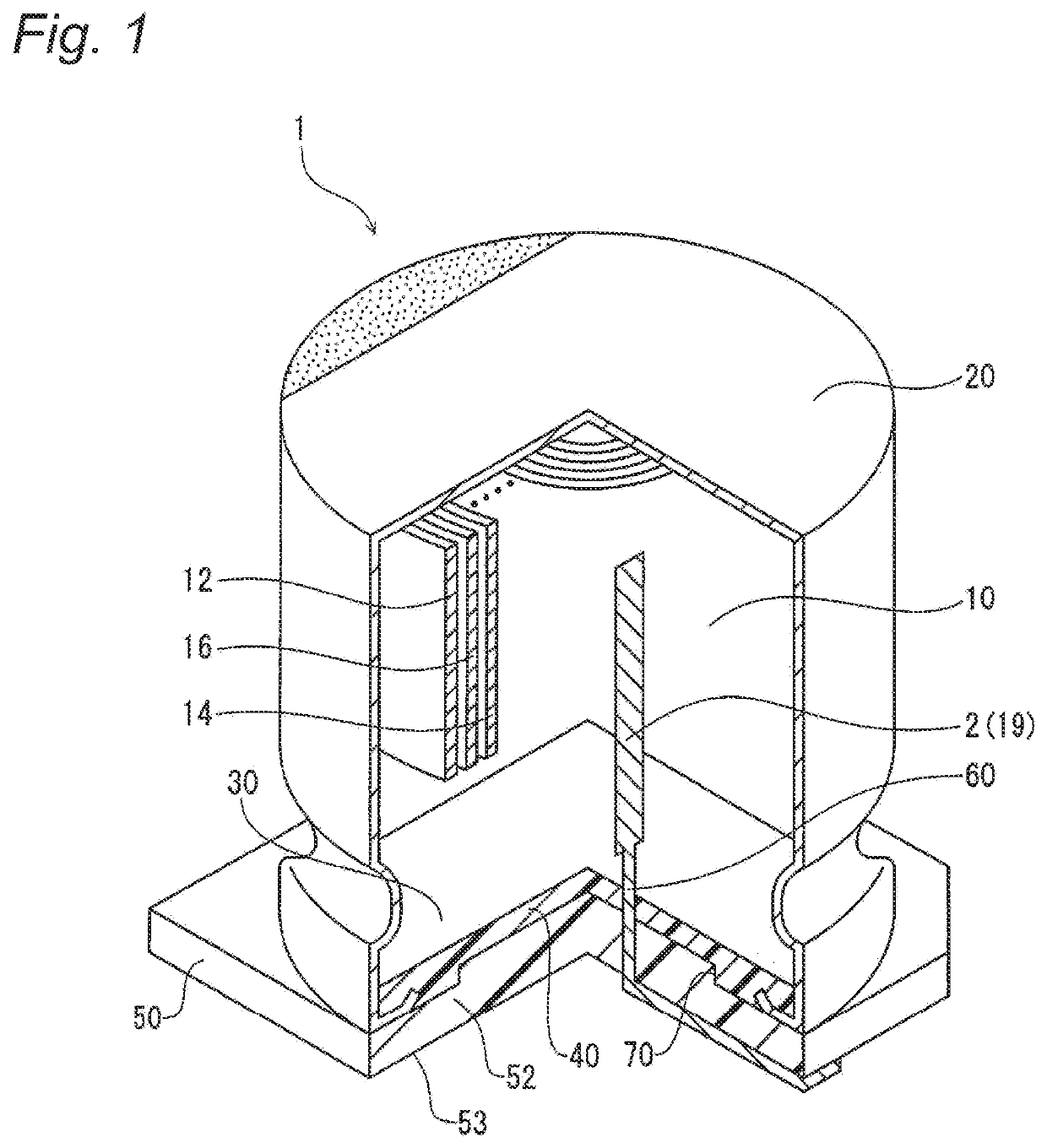
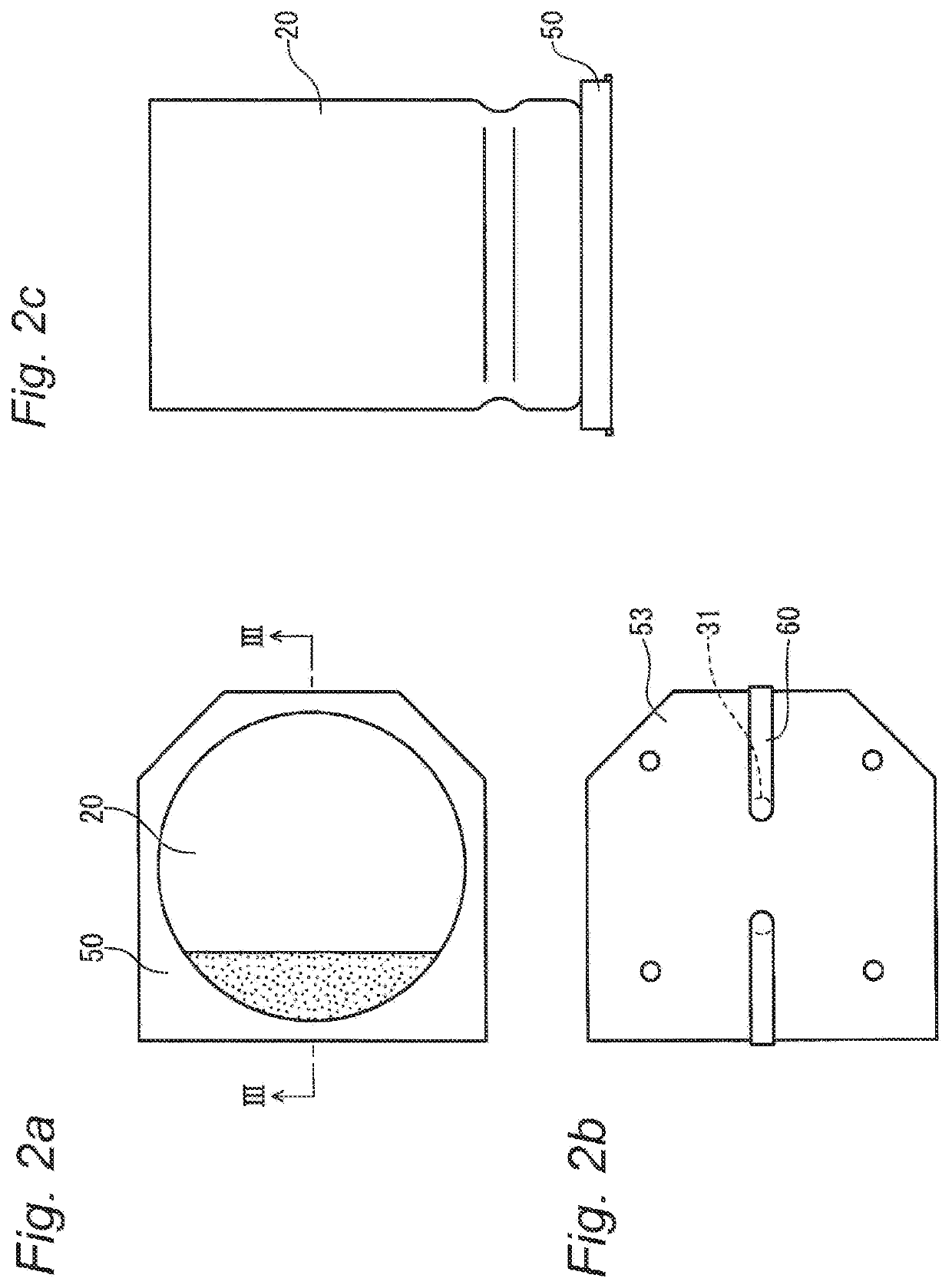
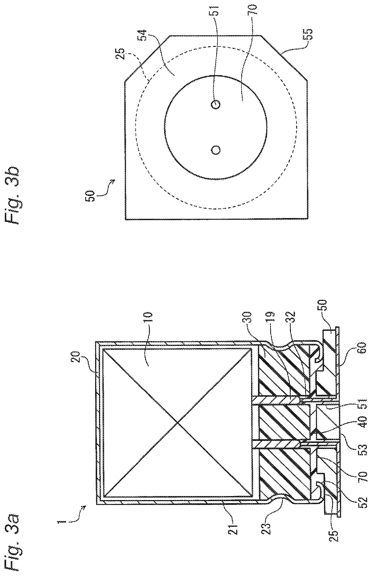
[0043]FIG. 1 is a partial broken-away perspective view partially showing the interior of an electrolytic capacitor 1 according to a first embodiment of the present invention. FIGS. 2(a) to 2(c) are a plan view, a bottom view, and a side view, respectively, of the electrolytic capacitor 1 shown in FIG. 1. As schematically shown in FIG. 1, the electrolytic capacitor 1 according to the first embodiment includes a capacitor element 10 including a pair of electrodes 2 (only one electrode 2 is shown in the drawing), an electrolyte (not shown) interposed between the pair of electrodes 2, a case 20 that accommodates the capacitor element 10 and the electrolyte and has an opening, a base plate 50 (also referred to as an “insulating plate”) having a pair of through holes 51 (FIG. 3), a resin member 40 (also referred to as an “adhesive material”) filled between the sealing member 30 and the base plate 50, and a pair of leads 60 connected to the pair of electrodes 2 of the capacitor element 10 ...

second embodiment

[0091]An electrolytic capacitor 1 according to a second embodiment of the present invention will be described with reference to FIGS. 17 to 27. The electrolytic capacitor 1 according to the second embodiment generally has the same configuration as that of the first embodiment, except that the base plate 50 includes at least one recess 75 on the resin bonding surface 52, in place of the protrusion 70, and therefore, descriptions of redundant details have been omitted.

[0092]FIG. 17 is a partial broken-away perspective view partially showing the interior of the electrolytic capacitor 1 according to the second embodiment of the present invention. A plan view, a bottom view, and a side view showing the outer shape of the electrolytic capacitor 1 according to the second embodiment are the same as FIG. 2(a) to 2(c) according to the first embodiment.

[0093]A capacitor element 10, a case 20, a sealing member 30, a resin member 40, and leads 60 (electrodes 2) that are used for the electrolytic...


PUM


Abstract

Disclosed is an electrolytic capacitor including: a capacitor element including a pair of electrodes; an electrolyte interposed between the pair of electrodes, a pair of leads electrically connected to the pair of electrodes, respectively; a case in which the capacitor element and the electrolyte are accommodated, and that has an opening, a sealing member that seals the opening, and has a pair of insertion holes for leading out the leads; an insulating plate having a pair of through holes for leading out the leads; and a resin member filled between the sealing member and the insulating plate, wherein the insulating plate has a resin bonding surface that abuts against the resin member, and a mounting surface opposed to the resin bonding surface, and includes at least one protrusion or recess on the resin bonding surface.

Description

TECHNICAL FIELD[0001]The present invention relates to an electrolytic capacitor, and particularly relates to an electrolytic capacitor including a resin member between a sealing member and a base plate. Note that the present application is based upon and claims the benefit of priority from the corresponding Japanese Patent Application Nos. 2017-167592 and 2017-167593 both filed on Aug. 31, 2017, the entire contents of which are incorporated herein by reference.BACKGROUND ART[0002]In general, due to their high reliability, electrolytic capacitors are being widely used, not only for consumer devices, but also as a part of vehicle-mounted circuits that are used under severe conditions. In particular, electrolytic capacitors used in an environment with high temperature and humidity, such as in an engine, are required to ensure operations, for example, at about 150° C. for the period of time on the order of several thousands of hours.[0003]A typical electrolytic capacitor includes a capa...

Claims


Application Information

Patent Timeline
IPC IPC(8): H01G9/10H01G9/008
CPCH01G9/008H01G9/10H01G2/02H01G9/08
Inventor MASUDA, MIYOKOTSUBAKI, YUICHIROAOYAMA, TATSUJIKUBO, DAISUKE
Owner PANASONIC INTELLECTUAL PROPERTY MANAGEMENT CO LTD
Why Eureka
Try Eureka