Receiving apparatus and non-transitory computer readable medium storing receiving processing program

Active Publication Date: 2020-12-31
JVC KENWOOD CORP A CORP OF JAPAN
View PDF0 Cites 1 Cited by
  • Summary
  • Abstract
  • Description
  • Claims
  • Application Information

AI Technical Summary

Benefits of technology

The patent is about a receiving apparatus or system that can detect and remove pulsed noise from a received signal. The system uses a bandwidth limiting filter to remove pulsed noise, but sometimes this results in the pulsed noise being extended in time and having reduced amplitude levels. To address this, the system includes a second pulse noise determining unit and a threshold controller that adjusts the detection and removal thresholds based on the results of the first and second pulse noise determining units. The technical effect of this invention is that it allows for more accurate detection and removal of pulsed noise from a received signal.

Problems solved by technology

However, the pulse noise after it passes the bandwidth limiting filter is extended in terms of time due to an influence of an impulse response of the bandwidth limiting filter, and an instantaneous amplitude level ends up being reduced.
Therefore, it is possible that this noise blanker may not be able to detect the pulse noise from the receiving signal after it passes the bandwidth limiting filter and this pulse noise may not be removed.
Further, even in a case in which the pulse noise is detected by this noise blanker and this pulse noise can thus be removed, the signal is attenuated for a period longer than the original pulse noise occurrence period, and thus the deterioration of the transmission signal ends up being increased.
That is, there is a problem that this noise blanker cannot remove the pulse noise with a high accuracy.
However, when the non-target signal has a high signal intensity, the difference between the signal intensity of the pulse noise and that of the non-target signal becomes small.
In this case, it becomes difficult to determine the pulse noise.
Therefore, there is a problem that this noise blanker cannot be able to remove the pulse noise with a high accuracy when the non-target signal has a high signal intensity.

Method used


Image

  • Receiving apparatus and non-transitory computer readable medium storing receiving processing program
  • Receiving apparatus and non-transitory computer readable medium storing receiving processing program
  • Receiving apparatus and non-transitory computer readable medium storing receiving processing program

Examples


first embodiment

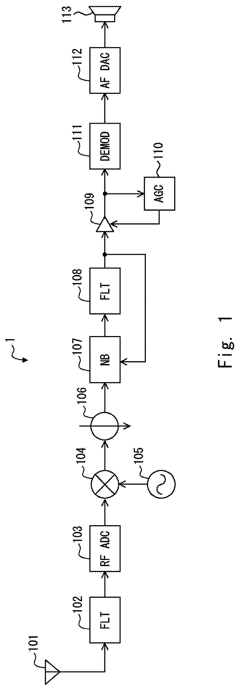
[0028]FIG. 1 is a block diagram showing a configuration example of a receiving apparatus 1 according to a first embodiment.

[0029]As shown in FIG. 1, the receiving apparatus 1, which is a so-called direct sampling receiving apparatus, includes an antenna 101, a filter 102, an AD converter 103, a mixer 104, a local oscillator 105, a decimation filter 106, a noise blanker 107, a bandwidth limiting filter 108, an amplifier 109, an automatic gain control circuit 110, a detector 111, a DA converter 112, and a speaker 113.

[0030]The antenna 101 receives a radio signal transmitted from a transmitting apparatus (not shown). The filter 102 performs filtering of a radio signal (a receiving signal) received by the antenna 101. The AD converter 103 performs sampling of a high-frequency receiving signal output from the filter 102 and outputs the resulting signal as a digital receiving signal. The mixer 104 mixes the receiving signal output from the AD converter 103 with an oscillation signal outpu...

second embodiment

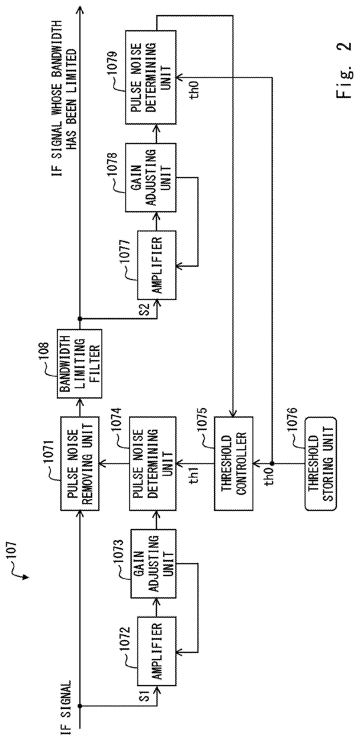
[0077]FIG. 18 is a block diagram showing a configuration example of a noise blanker 107a and a bandwidth limiting filter 108 provided in the receiving apparatus 1a according to the second embodiment.

[0078]As shown in FIG. 18, the receiving apparatus 1a includes the noise blanker 107a in place of the noise blanker 107 provided in the receiving apparatus 1. The noise blanker 107a further includes, besides the components of the noise blanker 107, a pulse noise removing unit 2071.

[0079]The pulse noise removing unit 2071 removes pulse noise included in the IF signal whose bandwidth has been limited by the bandwidth limiting filter 108 based on the result of the determination made by the pulse noise determining unit 1079. That is, the pulse noise removing unit 2071 removes the pulse noise that could not be removed by the pulse noise removing unit 1071.

[0080]Since the other configurations and operations of the noise blanker 107a and the receiving apparatus 1a are similar to those of the no...


PUM


Abstract

A receiving apparatus includes: a first pulse noise determining circuit configured to determine the presence or the absence of pulse noise in the receiving signal based on a first threshold; a first pulse noise removing circuit configured to remove pulse noise in the receiving signal based on the result of the determination made by the first pulse noise determining circuit; a bandwidth limiting filter configured to limit a receiving signal whose pulse noise has been removed by the first pulse noise removing circuit to a predetermined bandwidth; a second pulse noise determining circuit configured to determine the presence or the absence of pulse noise in the receiving signal whose bandwidth has been limited by the bandwidth limiting filter based on a second threshold; and a threshold control circuit configured to adjust a first threshold based on the result of the determination made by the second pulse noise determining circuit.

Description

CROSS REFERENCE TO RELATED APPLICATION[0001]This application is based upon and claims the benefit of priority from Japanese patent application No. 2019-118200, filed on Jun. 26, 2019, the disclosure of which is incorporated herein in its entirety by reference.BACKGROUND[0002]The present disclosure relates to a receiving apparatus and a receiving processing program, and relates to, for example, a receiving apparatus and a receiving processing program suitable for removing pulse noise with a high accuracy.[0003]In general, a receiving apparatus includes a bandwidth limiting filter that removes an untargeted signal included in a receiving signal by limiting the bandwidth of the receiving signal and a noise blanker that blocks propagation of extraneous pulse noise included in the receiving signal.[0004]For example, Japanese Unexamined Patent Application Publication No. H04-278729 discloses a receiving apparatus including a bandwidth limiting filter and a noise blanker. This receiving ap...

Claims


Application Information

Patent Timeline
IPC IPC(8): H04L25/03
CPCH04L25/03834H04L25/03993
Inventor NAIKI, YASUNORI
Owner JVC KENWOOD CORP A CORP OF JAPAN
Why Eureka
Try Eureka