
Optical element, transfer foil, authentication medium, and method of verifying authentication medium

a technology of optical elements and authentication mediums, applied in the field of optical elements, can solve the problems of difficult for the observer to find a suitable angular range for verification, the observer cannot observe the light having a predetermined color in the optical element, and the difficulty of clearly defining the colors that should be observed, so as to achieve the effect of facilitating the verification of authenticity

Active Publication Date: 2021-01-07
TOPPAN PRINTING CO LTD
View PDF0 Cites 1 Cited by
  • Summary
  • Abstract
  • Description
  • Claims
  • Application Information

AI Technical Summary

Benefits of technology

The present invention describes an optical element with several advantages. Firstly, it can be easily authenticated as it can show two different colors simultaneously. Secondly, the brightness of the optical element can be increased by adjusting the area ratio of each pixel region. Thirdly, the optical element can produce different colors in different regions due to the difference in the azimuth angle between the gratings. Additionally, the patent describes how the optical element can be modified to have equal obtuse angles for the gratings and different periods to achieve different colors in each region.

Problems solved by technology

Thus, since multiple colors are observed by the observer, it is difficult to clearly define the colors that should be observed when verifying the authenticity of such an optical element.
Furthermore, when verifying the authenticity of such an optical element, it is difficult for the observer to find a suitable angular range for verification from the angular range of observing the optical element.
Therefore, when such a subwavelength grating as an optical element is observed in a direction other than the specular reflection direction, the observer cannot observe the light having a predetermined color in the optical element.

Method used


Image

  • Optical element, transfer foil, authentication medium, and method of verifying authentication medium
  • Optical element, transfer foil, authentication medium, and method of verifying authentication medium
  • Optical element, transfer foil, authentication medium, and method of verifying authentication medium

Examples


first embodiment

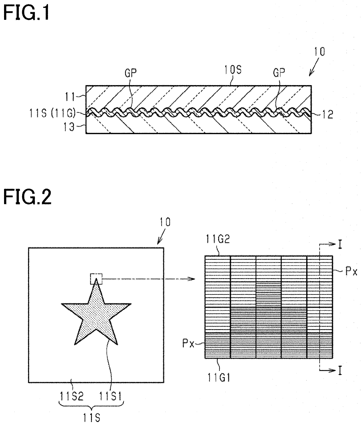
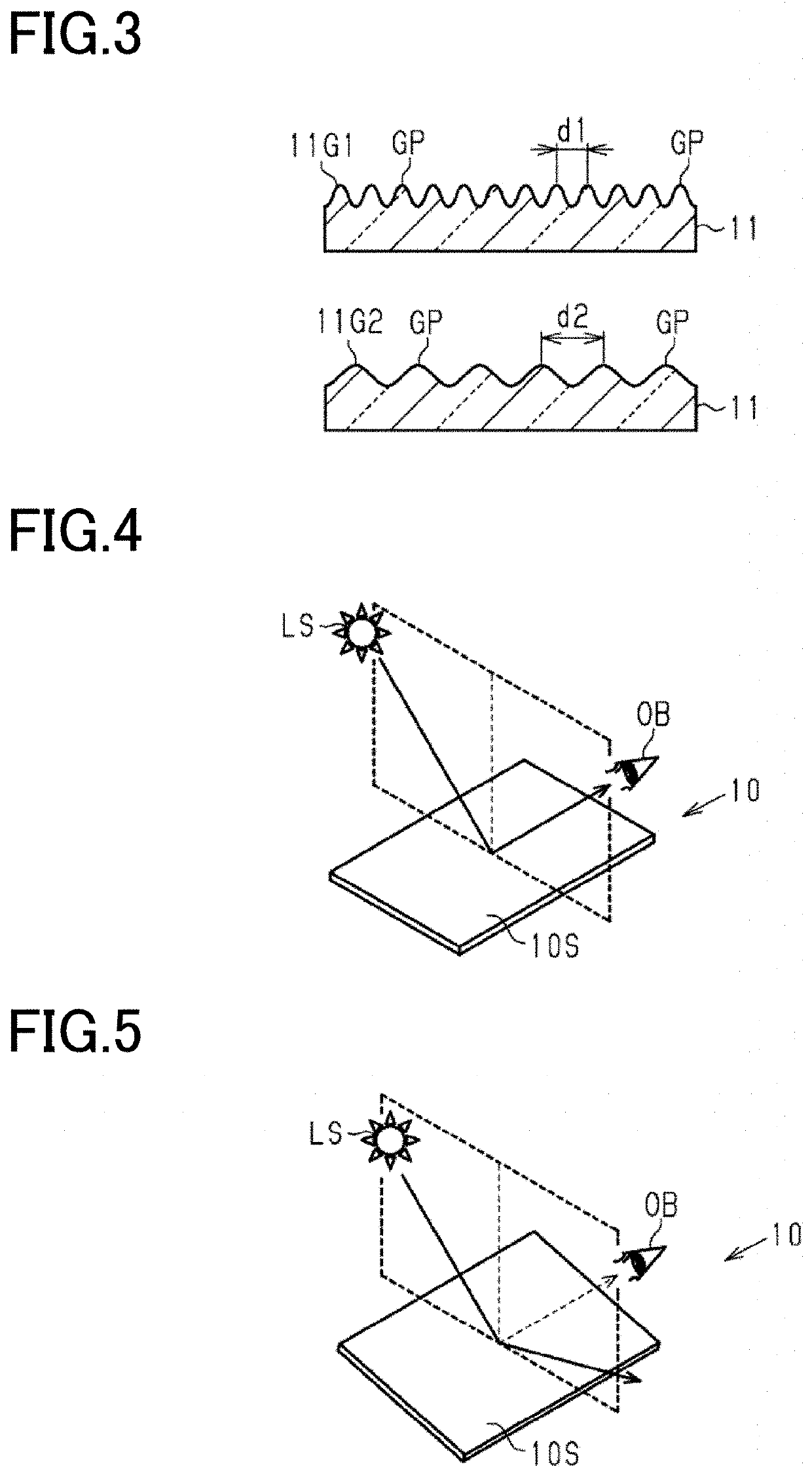
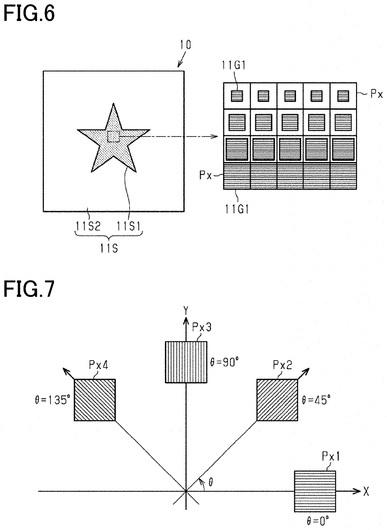
[0070]Referring to FIGS. 1 to 11, a first embodiment of an optical element of the present invention will be described. In the drawings, components exerting identical or similar functions are all denoted by the same reference signs to omit duplicate explanation. The embodiments of the present invention of the present disclosure are a group of embodiments based on one unique invention based on the Background Art. The aspects of the present disclosure are aspects of the group of embodiments based on one invention. Configurations of the present disclosure can have the respective aspects of the present disclosure. Features of the present disclosure can be combined to form the configurations. Thus, the features, configurations, aspects and embodiments of the present disclosure can be combined, and the combinations each have synergistic functions and can exert synergistic effects.

[0071]FIG. 1 shows an optical element 10 including a first layer 11, a second layer 12 contacting the first lay...

second embodiment

[0127]Referring to FIGS. 12 to 14, a second embodiment of the optical element will be described. The optical element according to the second embodiment of the present invention is different from the optical element of the first embodiment in the configuration of the grating patterns in the subwavelength grating. While the differences will be specifically described below, the components of the optical element of the second embodiment corresponding to those of the optical element of the first embodiment are given the same reference signs to omit duplicate description. In FIG. 12 to FIG. 14, for convenience of illustration, the subwavelength grating is shown as a structure where convexities are arranged being projected in a direction away from the flat surface. In the optical element of the second embodiment, the color of the subwavelength grating observed by the observer may be based on diffracted light of higher order than the zeroth-order diffracted light. Thus, in the following, th...

third embodiment

[0166]Referring to FIG. 15, an optical element according to a third embodiment will be described. The optical element according to the third embodiment of the present invention is different from the optical element 10 of the first embodiment in that the first layer includes a filler. While the differences will be specifically described below, the components of the optical element of the third embodiment corresponding to those of the optical element of the first embodiment are given the same reference signs to omit duplicate description.

[0167]FIG. 15 shows an optical element 30 including a first layer 11 made a resin in which a filler 31 is dispersed. The filler 31 has an average particle size of 400 nm or less. At least part of the light incident on the first layer 11 is scattered by the filler dispersed in the first layer 11. Therefore, the light incident on the subwavelength grating 11G includes light having incidence angles different from each other. Thus, grating patterns GP in ...


PUM


Abstract

A subwavelength grating displaying a colored image exhibiting a color corresponding to a grating period of a subwavelength grating in reflection directions including a specular reflection direction. A relief surface displaying a reflection image in monochromatic reflected light in reflection directions including a direction different from the specular reflection direction. An optical element has a first state in which neither a colored image nor a reflection image is displayed, a second state in which the colored image is mainly displayed, and a third state in which the reflection image is mainly displayed. A plane in which the optical element is disposed and a plane including a line of sight of an observer form an observation angle therebetween. The optical element is observed in any of the first, second and third states according to the observation angle.

Description

CROSS-REFERENCE TO RELATED PATENT APPLICATIONS[0001]This application is a continuation application filed under 35 U.S.C. § 111(a) claiming the benefit under 35 U.S.C. §§ 120 and 365(c) of International Patent Application No. PCT / JP2019 / 011841, filed on Mar. 20, 2019, which is based upon and claims the benefit of priority to Japanese Patent Application Nos. 2018-053545, filed on Mar. 20, 2018; and 2019-014299, filed Jan. 30, 2019, the disclosures of which are all incorporated herein by reference in their entireties.TECHNICAL FIELD[0002]Embodiments of the present invention relate to an optical element, a transfer foil, an authentication medium, and a method of verifying the authentication medium.BACKGROUND[0003]Optical elements using holograms, diffraction gratings, multilayer interference films and the like are affixed to securities such as gift certificates, banknotes and credit cards to prevent counterfeiting, and also affixed to articles for brand protection of the articles. Becau...

Claims


Application Information

Patent Timeline
IPC IPC(8): B42D25/328G02B27/42B42D25/324
CPCB42D25/328G02B5/1866B42D25/324G02B27/4205G07D7/003G07D7/12G07D7/1205G07D7/207G02B5/1809G02B5/1861G02B5/1819B42D25/373B42D25/425B42D25/29G07D2207/00
Inventor YAMAMOTO, HANAKOSUGIHARA, KEITAROTASHIRO, TOMOKOKAGOTANI, AKIHITO
Owner TOPPAN PRINTING CO LTD
Learn More