
Roller tool

a rolling tool and tool string technology, applied in the direction of roller bearings, borehole/well accessories, mechanical equipment, etc., can solve the problems of string damage, high risk of such components or parts falling off within the downhole environment, and catastrophic failure requiring immediate intervention at great risk and cost to the operator

Active Publication Date: 2021-01-07
WIRELINE ENG
View PDF10 Cites 8 Cited by
  • Summary
  • Abstract
  • Description
  • Claims
  • Application Information

AI Technical Summary

Benefits of technology

The patent describes a roller tool used in well tools that helps to rotate and position components within the tool. The tool includes a roller with a hub and a mandrel, and a set of bearings that improve the rotation between the hub and mandrel. A locking member can also be used to secure the connection between the roller and hub. Overall, this design helps to improve the performance and efficiency of the roller tool in well tools.

Problems solved by technology

Contact with the wall may lead to damage to the string, or jamming of the string downhole that may require at least partial retraction of the string before insertion is attempted again.
The more components there are within these roller tools, the higher the risk of such components or parts falling off within the downhole environment, for example as a result of a ballistic event downhole.
Any foreign objects such as fixings or wheels lost within the well can lead to catastrophic failure requiring immediate intervention at great risk and cost to the operator.

Method used


Image

  • Roller tool
  • Roller tool
  • Roller tool

Examples


Embodiment Construction

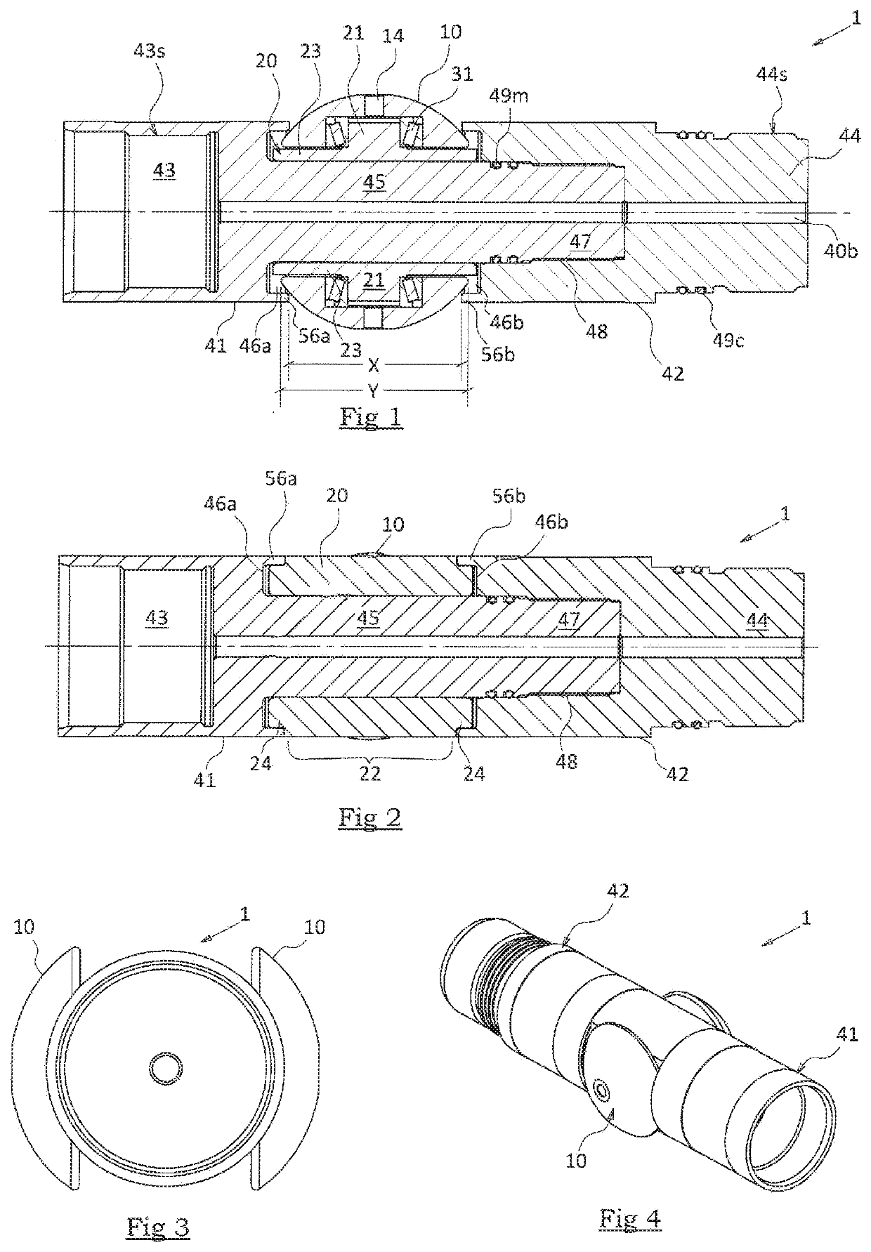
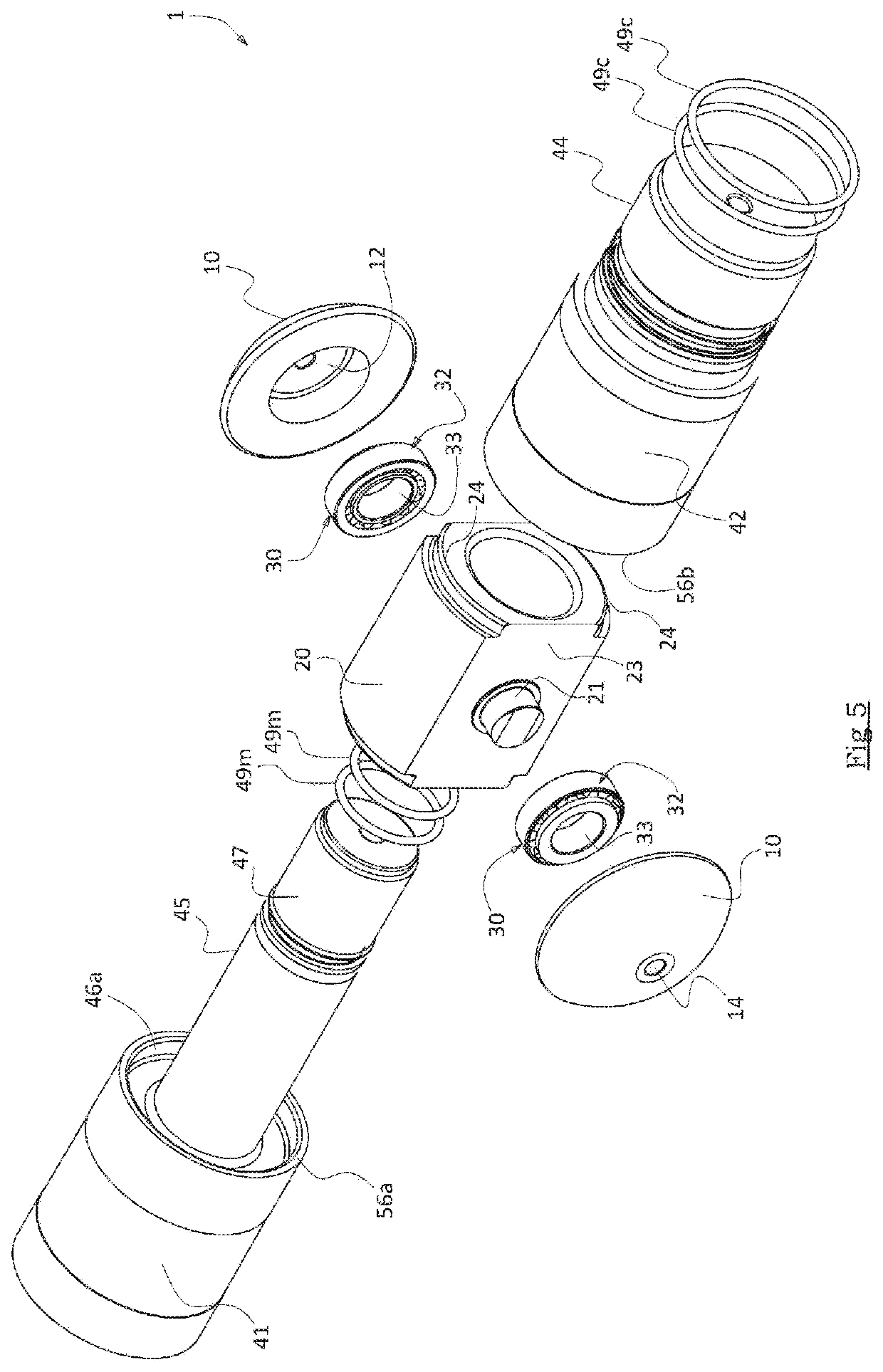
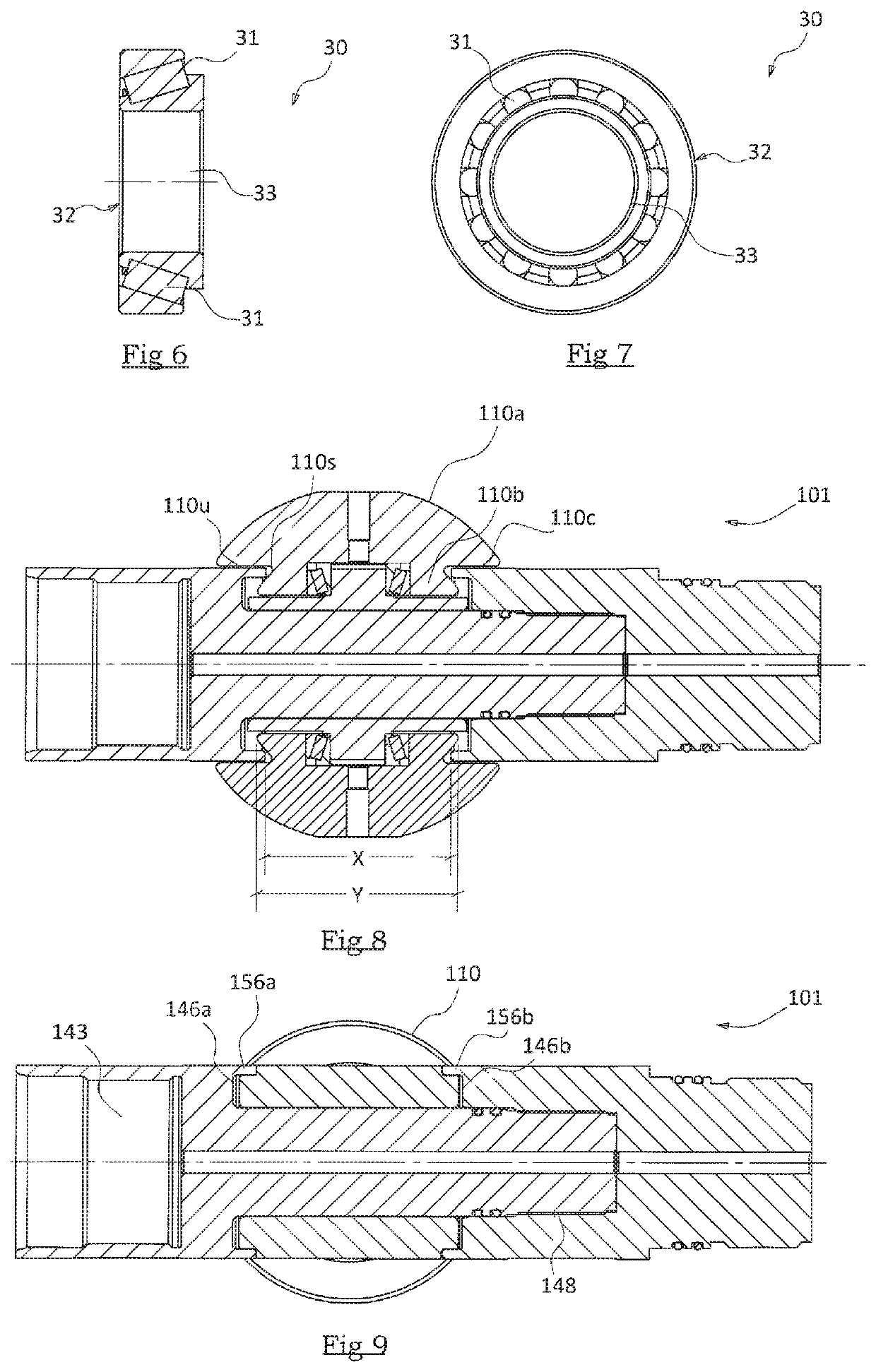
[0085]Referring now to the drawings, a roller tool 1 comprises two interconnecting tubular portions configured to form part of a string (not shown) deployed into or recovered from an oil or gas well (not shown), the interconnecting tubular portions comprising a first (male) connector 41 and a second (female) connector 42. An annular hub 20 is arranged to slide over a section of the first connector 41 and provide a connection point or hub 20 for the roller devices of the roller tools, here in the form of rollers or wheels 10, which are affixed to the hub 20 in use. The roller tool 1 is provided with suitable connections to allow it to be incorporated or included in the string, where the string may be a suitable tubular string such as a work string and in particular a wireline run string, a coiled tubing string or a drill pipe string. Alternatively, the roller tool 1 may be modified to allow it to be used on other types of downhole string such as casing or liner strings to be installe...


PUM


Abstract

A roller tool 1 that can be connected into a string for deployment into an oil or gas well includes at least two rollers or wheels 10 located on each side of the roller tool 1, with axes of rotation that are perpendicular to the axis of the roller tool 1. The roller tool further includes at least two interconnecting tubular portions, where one tubular portion 41 comprises a mandrel 45 that connects to another tubular portion 42. An annular hub 20 is fitted over the mandrel 45 and the rollers 10 are connected onto the hub 20. The tubular portions 41, 42 comprise circumferential sleeve sections 56a, 56b that partially extend over the rollers 10 and resist detachment of the rollers 10 from the roller tool 1. The roller tool 1 can aid passage of a string through a well by holding the string away from the walls of the well and reducing frictional contact.

Description

[0001]The present invention relates to a roller tool, in particular a roller tool for use within an oil or gas well. More particularly, the invention relates to a roller tool suitable for use with a downhole sub.BACKGROUND OF THE INVENTION[0002]Deployment of a downhole tool string (whether that be on a drill pipe, coiled tubing, wireline, slickline, workstring or other means or conveyance), particularly in deviated wells (into an oil or gas well or recovery therefrom) may be facilitated by attachment of one or more roller tools within the string. The roller tool(s) hold the string away from the sides of the wellbore to reduce interference from debris or other inconsistencies in the walls of the bore that may lead to the string bellying out on the wall of the wellbore. Contact with the wall may lead to damage to the string, or jamming of the string downhole that may require at least partial retraction of the string before insertion is attempted again. Moreover, the roller tool(s) red...

Claims


Application Information

Patent Timeline
IPC IPC(8): E21B17/10F16C19/36
CPCE21B17/1057F16C19/364E21B17/10E21B23/001E21B4/18E21B23/14
Inventor CHURCH, PAUL ANDREWJOINER, PETER ALANELRICK, ANDREW JOHNMACLEOD, IAIN MORRISON
Owner WIRELINE ENG
Learn More