Method and apparatus for optical confocal imaging, using a programmable array microscope

Pending Publication Date: 2021-01-07
MAX PLANCK GESELLSCHAFT ZUR FOERDERUNG DER WISSENSCHAFTEN EV
View PDF5 Cites 1 Cited by
  • Summary
  • Abstract
  • Description
  • Claims
  • Application Information

AI Technical Summary

Benefits of technology

[0025]As a further advantage of the invention, the camera pixels of the camera device (c and/or nc channel) responding to light received from the individual modulator elements, i.e. the pixelwise camera signals, preferably provide distinct, unique and stable distributions of relative camera signal intensities associated with their coordinates in the matrix of camera pixels, which are mapped to the corresponding modulator elements using the calibration procedure. The distribution is described with a system of linear equations defining the response to an arbitrary distribution of intensities originating from the modulator elements.
[0026]Advantageously, various mapping techniques are available. According to a first variant (centroid method), all collected calibration pattern images are accumulated (superimposing of the image signals of the whole sequence of illumination patterns) and camera signals are mapped back to their corresponding originating modulator elements, wherein centroids of the camera signals define a local sub-image in which intensities are combined by a predetermined algorithm, like e.g. the arithmetic or Gaussian mean value of a 3×3 domain centered on the centroid position, so as to generate a signal intensity assignable to the corresponding originating modulator image element. The same procedure is applied independently to the conjugate and non-conjugate channels, resulting in a registration of the two in the coordinate system of the modulator elements
[0027]According to a second variant (Airy aperture method), all collected images are accumulated and camera signals are mapped back to their corresponding originating modulator elements again. The image signals of the whole sequence of illumination patterns are superimposed. The illumination patterns comprise illuminations apertures with a dimension which is comparable with the Airy diameter (related to the centre wavelength of the excitation light). In this case, every signal at every position in the image resulting from overlapping camera responses to an entire pattern sequence is represented with the linear equation with coefficients known from the calibration procedure, and the corresponding emission signals impinging on the corresponding modulator elements are obtained by the solution to the system of linear equations describing the entire image. Accordingly, the camera signals representing the respon

Problems solved by technology

However, the conventional PAM operation procedures may have limitations in terms of spatial imagin

Method used


Image

  • Method and apparatus for optical confocal imaging, using a programmable array microscope
  • Method and apparatus for optical confocal imaging, using a programmable array microscope
  • Method and apparatus for optical confocal imaging, using a programmable array microscope

Examples


Embodiment Construction

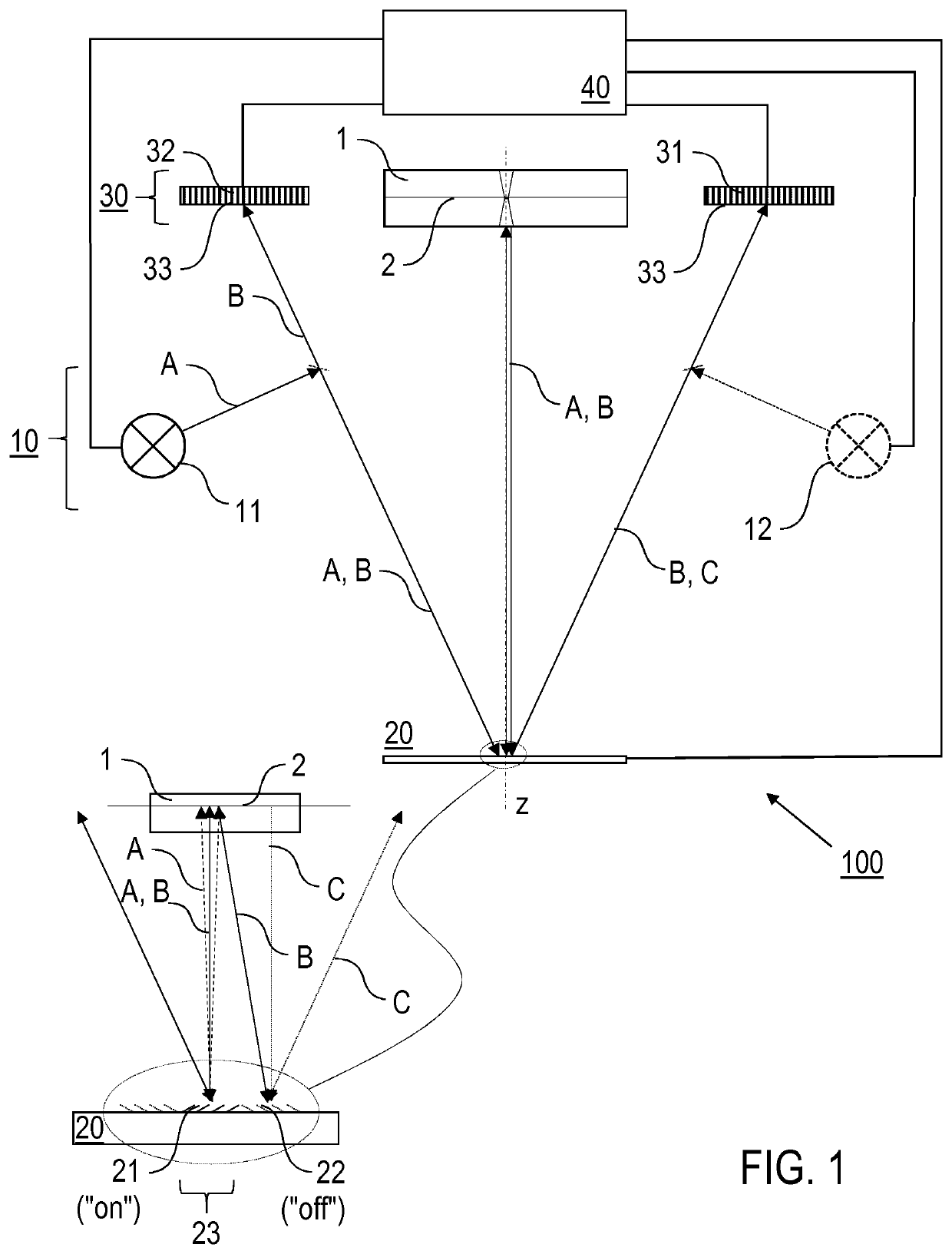
[0041]The following description of preferred embodiments of the invention refers to the implementation of the inventive strategies of individual image acquisitions, while trading speed for enhanced resolution, on the basis of three PAM operation modes, all of which retain optical sectioning. They incorporate acquisition and data processing methods that allow operation in three steps of improving lateral resolution of imaging. The first PAM operation mode (or: RES1 mode) is based on employing the inventive calibration, resulting in a lateral resolution equal to or above 200 nm. The second PAM operation mode (or: RES2 mode) is based on employing the inventive extraction of the conjugate image from the non-conjugate camera channel, allowing a reduction of the illumination aperture and resulting in a lateral resolution in a range from 100 nm to 200 nm. The third PAM operation mode (or: RES3 mode) is based on advanced fluorescence techniques, resulting in a lateral resolution below 100 n...


PUM


Abstract

Optical confocal imaging, being conducted with a programmable array microscope (PAM) (100), having a light source device (10), a spatial light modulator device (20) with a plurality of reflecting modulator elements, a PAM objective lens and a camera device (30), wherein the spatial light modulator device (20) is configured such that first groups of modulator elements (21) are selectable for directing excitation light to conjugate locations of an object to be investigated and for directing detection light originating from these locations to the camera device (30), and second groups of modulator elements (22) are selectable for directing detection light from non-conjugate locations of the object to the camera device (30), comprises the steps of directing excitation light from the light source device (10) via the first groups of modulator elements to the object to be investigated, wherein the spatial light modulator device (20) is controlled such that a predetermined pattern sequence of illumination spots is focused to the conjugate locations of the object, wherein each illumination spot is created by at least one single modulator element defining a current PAM illumination aperture, collecting image data of a conjugate image lc, based on collecting detection light from conjugate locations of the object for each pattern of PAM illumination apertures, collecting image data of a non-conjugate image lnc, based on collecting detection light from non-conjugate locations of the object for each pattern of PAM illumination apertures via the second groups of modulator elements (22) with a non-conjugate camera channel of the camera device (30), and creating an optical sectional image of the object (OSI) based on the image data of the conjugate image lc and the non-conjugate image lnc, wherein the step of collecting the image data of the conjugate image lc includes collecting a part of the detection light from the conjugate locations of the object for each pattern of PAM illumination apertures via modulator elements of the second groups of modulator elements (22) surrounding the current PAM illumination apertures with the non-conjugate camera channel of the camera device (30). Furthermore, a PAM calibration method and PAMs being configured for the above methods are described.

Description

FIELD OF THE INVENTION[0001]The present invention relates to optical confocal imaging methods which are conducted with a programmable array microscope (PAM). Furthermore, the present invention relates to a PAM being configured for confocal optical imaging using a spatio-temporally light modulated imaging system. Applications of the invention are present in particular in confocal microscopy.TECHNICAL BACKGROUND[0002]EP 911 667 A1, EP 916 981 A1 and EP 2 369 401 B1 disclose PAMs which are operated based on a combination of simultaneously acquired conjugate (c, “in-focus”, Ic) and non-conjugate (nc, “out-of-focus”, Inc) 2D images for achieving rapid, wide field optical sectioning in fluorescence microscopy. Multiple apertures (“pinholes”) are defined by the distribution of enabled (“on”) micromirror elements of a large (currently 1080p, 1920×1080) digital micromirror device (DMD) array. The DMD is placed in the primary image field of a microscope to which the PAM module, including ligh...

Claims


Application Information

Patent Timeline
IPC IPC(8): G02B21/00
CPCG02B21/008G02B21/0076G02B21/0048G02B21/0032G02B21/0084G02B26/0841
Inventor JOVIN, THOMAS M.DE VRIES, ANTHONY H. B.ARNDT-JOVIN, DONNA J.
Owner MAX PLANCK GESELLSCHAFT ZUR FOERDERUNG DER WISSENSCHAFTEN EV
Why Eureka
Try Eureka